Как выбрать гостиницу для кошек
14 декабря, 2021
 The equatorial tracking system with linear actuators developed on the platform of Transilvania University of Bra§ov is presented in fig. 3. Panel 1 is assembled on a frame made of L profiles 2 mounted along the panel welded together by another two L profiles numbered 3. At the middle of the L profiles 3, bearings 4 and 5 together with the U profile central beam 6 create the daily rotational axis of the panel. The daily rotational movement (with angle P) is performed with the screw linear actuator 10, attached by the rotational link 11 on the rectangular beam 9 mounted with screws on the central beam. The end of the actuator’s screw is attached with rotational link on the bolt of the brida 12 mounted on the L profile 3.
The altitudinal (season) movement is performed around the rotational axis made of bearings 7 linking the middle of the central beam 6 with the pillar 8. The seasonal rotational movement (with angle y) is performed with the screw linear actuator 14, attached on the pillar 8 with the rotational link 15. The end of the actuator’s screw is attached with rotational link on the lever 13 mounted on the central beam 6.
 |
 |
With the purpose of diminishing the friction, double sealed ball bearings are used for the main rotational axes of the tracking system. Figure 4 presents a longitudinal section through the bearing 4 of the daily rotational axis. The journal part 16, on which the inner ring of the bearing is mounted, is assembled on part 3. The cap 17, on which the outer ring of the bearing is mounted, is assembled on the part 18 belonging to the central beam 6.
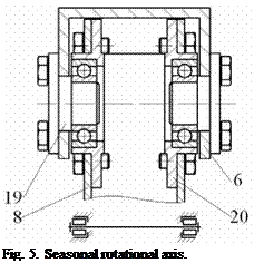
Figure 5 presents a longitudinal section through the bearings 7 of the seasonal rotational axis. The journal part 19, on which the inner ring of the bearing is mounted, is assembled on the central beam 6. The cap 20, on which the outer ring of the bearing is mounted, is assembled on the pillar 8.
|
|
|
Figure 6 presents extreme positions of the panel rotating around the daily axis (a, b) and around the seasonal axis (c, d). |
|
abed |
Fig. 6. Specific positions.