Как выбрать гостиницу для кошек
14 декабря, 2021
C. Estrada1*, D. Riveros-Rosas1, J. Herrera-Vazquez2, Sergio Vazquez-Montiel2, Camilo A. Arancibia-Bulnes1, C. Perez-Rabago1, F. Granados-Agustfn.
1 Centro de Investigation en Energia, Universidad Nacional Autonoma de Mexico. Av. Xochicalco s/n;
Temixco, 62580 Morelos, Mexico.
2 Institute Nacional de Astrofisica, Optica y Electronica. Luis Enrique Erro 1, Tonantzintla, A. P. 216, 72000
Puebla, Mexico.
* Corresponding author, cestrada@cie. unam. mx
Abstract
In the present work, the optical design for a new high radiative flux solar furnace is described. Several optical configurations for the concentrator of the system have been considered. Ray tracing simulations were carried out in order to determine the shape and intensities of the concentrated radiative flux distributions in the focal zone of the system, for comparing the different proposals. The best configuration was chosen in terms of maximum peak concentration, but also in terms of economical and other practical considerations. It consists of an arrangement of 409 first surface spherical facets with hexagonal shape, placed on a spherical supporting structure. The facets have corrected orientations in order to compensate for aberrations. The design considers an intercepted power of 30 kWt and a target peak concentration above 10,000 Suns. For the design, global optical errors from 0 to 6 mrad have been considered, but it is found that the maximum tolerable overall error will be of 4 mrad.
Modern solar furnace technology starts in the 1950s decade. The first research in these devices was directed towards studying the effects of high temperatures (around 3500°C) on the properties of different materials exposed to highly concentrated solar fluxes [1]. Among their applications is the study of properties like thermal conductivity, expansion coefficients, emissivity, melting points [2], study of ultra refractory materials, and determination of phase diagrams, crystal growth, and purification of materials. At the same time, methods for the measurement of high temperatures in receivers [3], and the flux density of concentrated radiation [4] have been developed. The latter have evolved and image digitalization techniques are used [5], with calorimetric techniques as reference for the images [6].
Among the first built, there were the furnace of Arizona State College in the USA, in 1956 [7], and the furnace of the Government Institute for Industrial Research, in Japan. Solar furnace technology has evolved, and larger furnaces with higher concentration factors have been built, like the one of the CNRS in Odeillo, France, with 1000 kW [8]; the furnace of the Academy of Sciences of Usbekistan, with 1000 kW [9]; the furnace of Paul Scherrer Institute (PSI), of 25-40 kW [10]; the furnace of CIEMAT, in Plataforma Solar de Almeria, Spain, with 45 kW; and the furnace of DLR, in Cologne, Germany, of 20 kW [11].
Mexico has an ideal position for the implementation of solar technologies, due to its favorable geographical location in the Sunbelt of the planet. The estimation is a yearly average of more than 5.5 kWh per square meter of global solar radiation over the country. In particular, in the northwest states this insolation has a very important component of beam solar radiation. This high quality
solar resource makes that area ideal for the implementation of concentrating solar technologies (CST), either for electrical power generation or for the production of solar fuels as Hydrogen. For these reasons, the construction of a high radiative flux solar furnace (HRFSF) was proposed, as a research tool to allow the development of CST in Mexico. Federal funding for the development of this infrastructure has been approved by CONACYT, and the project is now in progress. The HRFSF will be developed in three years, starting from September 2007, by the Centro de Investigacion en Energia of Universidad Nacional Autonoma de Mexico (CIE-UNAM), in collaboration with Instituto Nacional de Astrofisica, Optica y Electronica (INAOE), and other institutions. The applications of this infrastructure are expected to be in the areas of solar chemistry and solar materials processing [12].
The design targets for the HRFSFS are a thermal power of 30 kW, peak concentration above 10000 suns, and a solar spot of 10 cm diameter or smaller. To achieve these targets, the design was carried out by means of ray tracing simulations, to optimize the optical characteristics of the system.
We started from an initial proposal of a faceted concentrator of around 30 kW, formed by polished first surface glass mirrors with spherical curvature. From the results reported in [13] about the influence of the number of facets in the concentration factors, we sought that the concentrator had the largest feasible number of facets. The size of 40 cm was selected, on the basis of fabrication and mounting considerations. The shape of the facets was chosen to be hexagonal, because this geometry fills adequately the concentrator surface, still being relatively easy to polish. From the point of view of filling the space, square facets would be an interesting option also, but they are difficult to polish adequately.
Also, from the results of [13], it was decided to mount the mirrors on a curved frame, either spherical or parabolic, instead of a flat structure (like from instance in the DLR [11] or in NREL), which would be the easiest option. This has the advantage of reducing the average distance of the facets to the focal point, and therefore reducing the spread of the reflected solar cones.
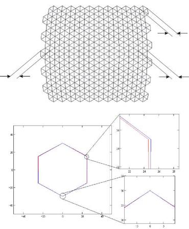
In Fig. 1, the hexagonal mirrors mounted on a circular frame are projected onto a flat surface. The shape of each mirror must be designed according to this projection to minimize mutual shading.
For this, the vertical dimensions of the mirrors were not altered, changing only the horizontal dimensions in order to fit the mirrors on the arrangement. The difference with respect to regular hexagons is actually small, but it must be taken into account in the fabrication of the facets.
In the present optical system the spherical aberration of the facets is important. Due to this aberration and, in a smaller degree, to comma and astigmatism, the focal region is increased in size (Fig. 2). Facets that are on the most external parts of the concentrator contribute more to these aberration effects, because they are facing the incoming radiation with more inclination.
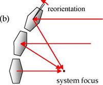
Aberrations can not be corrected with additional optical surfaces in a system like this. A lot of improvement can be made however, by reorienting the facets to different inclinations. The angle for each facet is chosen such that the ray reflected on the center of the facet is effectively directed towards the focal point of the system, as illustrated in Fig. 3. In this way, even though the facets are mounted on a spherical frame, they are not tangent to the surface of the frame.
|
|
|
|
|
|
|
Figure 2. Effects of the spherical aberration.
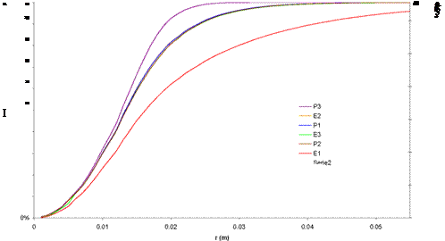
In addition to the reorientation of the facets, using different focal distances for each one may also help to compensate for the aberrations. Several cases were simulated, which are compared against a continuous paraboloid of equivalent area and focal distance:
• E1: Sphere with reoriented facets. All facets with the same focal distance.
• E2: Sphere with reoriented facets. All facets with a different focal distance, calculated according to their distances to the actual focus.
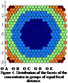
• E3: Sphere with reoriented facets. Facets in six different groups of equal focal distance.
• P1: Paraboloid with reoriented facets. Similar to case E2, but with paraboloidal frame.
• P2: Paraboloid with reoriented facets. Focal distances in groups, as case E3.
• P3: Continuous paraboloid.
 |
 |
In configurations E3 and P2, only six different focal distances are used, on the assumption that the optical performance could be reasonably good, as compared to the case in which every facet has its own focal distance. This possibility is explored because restricting the number of different focal distances would be very advantageous to reduce fabrication costs. The groups of facets are shown in Fig. 4, and their data reported in Table 1.
Figure 3. Reorientation of facets (b) for correction of the spherical aberration (a).
The modeling of the above configurations was carried out under the assumption of perfect specular reflection; i. e., reflectivity equal to unity and zero optical errors. Based on the results obtained, one of these configurations was selected for further investigation. This configuration was then simulated with different values of the optical error, in order to determine the maximum tolerable value of this parameter for the construction of the system.
 >
>
Each simulation run was carried out with two ray trace codes of different nature, to ensure the reproducibility of the results. The first one called Tonalli [13, is a code based on the convolution method [14], and developed in collaboration between CIE-UNAM (Mexico) and CIEMAT, Spain. The second was a routine for reprocessing the results from a commercial optical design software, called Zemax.
|
Table 1. Groups of focal distances considered for cases E3 and P3
|
T he results for the different configurations are presented in Table 1 and Fig. 6. The best result is, as expected, for the control case of a continuous paraboloid (P3). On the other hand, the four configurations E2, E3, P1, and P2, are very similar to each other; there is practically no difference in peak concentration between the paraboloidal and spherical frames, either when all facets have different focal distances (E2 and P1), or when they are grouped in six focal distances (E3 and P2). The case with a single focal distance (E1) is the worst of all, indicating that it is at lest necessary to consider a few different values for the focal distance. Five or six turned out to be a good number in preliminary analyses.
|
Table 2. Results of the simulations for the proposed configurations.
|
Once it was determined that a spherical frame is a good option, the next step consisted in studying the effect of the curvature radius of this frame. It was considered that a smaller radius could improve the concentration by reducing the distance the reflected solar cones travel, and therefore limiting the spread of the solar image. In Fig. 6 the variation of peak concentration with curvature radius is presented. It is observed that the best concentration is obtained for curvature radius between 500 and 550 cm. However, the concentration factor for the studied cases has a maximum variation of only 1.3%. on the other hand, the rim angle of the concentrator increases considerably as the radius of curvature is reduced. A large rim angle may result inconvenient for the implementation of receivers in the focal zone, due to the large incidence angles of radiation, as illustrated in Fig. 7. So there is little to gain from the reduction of the radius and there are potential problems with this. Therefore a radius of 7.5 m was fixed for the following simulations, giving a effective focal distance of 3.68 m.
 |
The next study was to analyze the effects of optical errors in the performance of the concentrator. For this purpose, the E3 configuration was considered. Reflectivity was taken as 0.81 and focal distances according to the previously described groups. In Fig. 8 the results are presented for peak concentration, average concentration and spot radius (for 90% collected power). We can see that with values of the optical error between 3 and 4 mrad, the peak concentration is between 15000 and 10500 suns, while spot radius would be between 4 and 5 cm. So, a maximum optical error of 4mrad is required to meet the design targets stated above for the solar furnace.
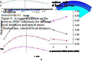
It is known that optical errors modify not only the concentration factor but also other characteristics of a faceted concentrator, like the optimal focal distance [13]. In Fig. 9 we present
 |
 |
the average irradiance values for different focal distances and optical errors. In this case we consider a configuration of the type E2.
As can be seen from Fig. 8, even tough there is a dependence of the optimal focal distance with optical error, the variation is not sharp. The previously selected focal distance of 3.68 m is well within the optimal range for the errors considered.
It must be pointed out, that the optical error we are considering here is the global error of the system. This includes the alignment and surface errors of the facets, but also the alignment, surface, curvature, and tracking errors of the heliostat. Therefore, the upper bound of 4 mrad must accommodate for all of these effects. Actually, the type of facets considered can be fabricated with very high accuracy, and also an accurate alignment procedure is being developed for the facets of the concentrator. Therefore, the design of the heliostat may prove to be the more critical problem.
A specific heliostat design is in process, where the target would be to minimize all optical errors.
The design of the HRFSF aims to create a high quality infrastructure for research in solar concentration systems in Mexico. The design considers a faceted concentrator, formed by 409 hexagonal first surface polished glass mirrors. The mirrors will be attached to a frame of spherical curvature. Ray tracing results indicate that there is very little difference in optical performance between a parabolic and a spherical frame, but the latter may be easier to fabricate. It was found that it is not convenient to use mirrors of equal focal distances, mounted tangent to the frame curvature. Instead, mirror should have different focal distances and must be tilted with respect to the frame. This helps compensating for the optical aberrations. It was found that grouping the mirrors in 6 sets of equal focal distances gives very good results. Also, the effect of optical errors was investigated. It was found that error must be below 4 mrad to reach the design targets.
This work was partially supported by CONACYT (Grant 56918) and UNAM (Grant 372311721).
D. Riveros-Rosas and J. Herrera-Vazquez acknowledge graduate scholarships from CONACYT.
[1] Glaser, P. E. Solar Energy, 2 (1958) 7-10.
[2] Hisada, T., Mii, H., Noguchi, C., Noguchi, T., Hukuo, N., and Mizuno, M., Solar Energy, 1 (1957) 14-18.
[3] Brenden, B. B. et al. Solar Energy, 2 (1958)13-17.
[4] Loh, Eugene et al., Solar Energy, 1 (1957) 23-26.
[5] Jonhnston, G., Journal of Solar Energy Engineering, 117 (1995) 290-293.
[6] Perez-Rabago, C. A., Marcos, M. J., Romero, M., Estrada, C. A., Solar Energy 80 (2006) 1434-1442.
[7] Kevane, C. J., Solar Energy, 1 (1957) 99-101.
[8] Trombe, F., Le Phat Vinh, A., Solar Energy, 15 (1973) 57-61.
[9] Abdurakhamanov A. A. et al. Applied Solar Energy, 34 (1998).
[10] Schubnell, M., M., Kelle, J., Imhof, A, Journal of Solar Energy Engineering, 113 (1991) 112-116.
[11] Neumann, A., Groer, U., Solar Energy, 58 (1996) 181-190.
[12] Fletcher, E. A., Journal of Solar Energy Engineering, 123 (2001) 63-74.
[13] Riveros-Rosas, D., Sanchez-Gonzalez, M., Arancibia-Bulnes, C., Estrada, C., EUROSUN Congress, Lisbon, Portugal. October 7-10, 2008.
[14] Biggs, F., Vittitoe, C. N.. “Helios model for the optical behavior of reflecting solar concentrators”. Sandia National Laboratories Report, SAND 76-0347, Albuquerque, USA (1979).
[1] Introduction
Solar desalination, an environment-friendly technique, is successfully used for the production of fresh water from saline seawater in many parts of the world. In the last decade, with the rise of fuel cost, an extensive research has been carried out by different institutions worldwide to develop an efficient way of utilizing solar energy for water desalination.
The heat pump is a useful device in transforming low-grade thermal energy into a usable energy source. Heat pumps can use many sources, such as ground [1], to provide useful energy for