Как выбрать гостиницу для кошек
14 декабря, 2021
The described sensitivity analysis methods are implemented into the Genopt (Generic optimization program) [4] and coupled with the simulation program TRNSYS. For the first system, the influence of 16 parameters on the target function, describing the overall cost of the system in ct/kWhsolar, was investigated by the Morris method. Results of the analysis are presented in the Table 1.
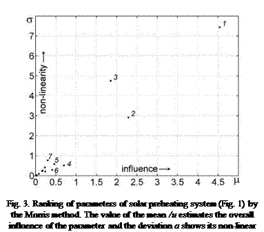
Table 1. Ranking of the parameters by their influence on the cost target function by the Moris method. The
value of the mean /и estimates the overall influence of the parameter and the deviation a shows its non-linear
effect.
|
N |
Parameter |
Variation range |
и |
5 |
|
|
1 |
^dis, max |
Max. discharge spec. volume flow |
[10; 15] in L/m2h |
4.54 |
7.44 |
|
2 |
vsol, p |
Specific volume flow |
[6; 10] in L/m2h |
2.29 |
2.92 |
|
3 |
Dvive |
Pipe deameter |
[20; 30] in mm |
1.85 |
4.75 |
|
4 |
Vstore |
Volume of solar storage |
[4000; 8000] in Liter |
0.46 |
0.58 |
|
5 |
Aon |
Collector slope |
[30; 46] in o |
0.70 |
0.51 |
|
6 |
^Thyst |
Hyst. for contr. pump in sec. circ |
[1; 7] in K |
0.41 |
0.29 |
|
7 |
Hch1 |
Rel. pos. of inlet 1 |
[0.6; 1] |
0.30 |
0.77 |
|
8 |
Hch2 |
Rel. pos. of inlet 2 |
[0.1; 0.6] |
0.24 |
0.21 |
|
9 |
Sh1 |
Rel. pos. of temp. sensor 1 |
[0.1; 0.5] |
0.23 |
0.41 |
|
10 |
ATU |
Temp. diff. to switch off the pump |
[0; 7] in K |
0.16 |
0.23 |
|
11 |
Sh2 |
Rel. pos. of temp. sensor 2 |
[0.55; 0.75] |
0.18 |
0.26 |
|
12 |
UAshe |
UA value of the sol. heat exch. |
[70; 130] in W/m2K |
0.08 |
0.09 |
|
13 |
У coll |
Scaling factor |
[-5; 6] in o |
0.03 |
0.02 |
|
14 |
Ghyst |
Hyst. for contr. pump in sol. circ. |
[2; 50] in W/m2 |
0.02 |
0.02 |
|
15 |
Amin |
Switch-off threshold for pump |
[40; 200] in W/m2 |
0.01 |
0.02 |
|
16 |
Sh3 |
Rel. pos. of temp. sensor 3 |
[0.8; 1] |
0.00 |
0.00 |
In Fig. 3 the mean и of the distribution G; versus the standard deviation a of the distribution F is given. The larger the value of the mean и. the larger the overall influence of the parameter. Large values of the standard deviation a mean strong non-linear effect of the parameter or its interaction with other parameters. It is seen that parameters 1-3 (the maximal power of two pumps in charging and discharging circuits and the diameter of pipes) are the most important and influence the target function both linearly and non-linearly. Parameters 4-7 could be considered as average important and the other 9 parameters as not important.
 |
|
The second system has been investigated with the FAST. The target function is chosen as the fractional thermal energy savings :
![image287 Подпись: Table 2. Sensitivity of parameters of the reference system determined with the FAST algorithm. Parameter Variation range Test 1 Collector area [20; 100] in m2 0.8144 Store volume [3; 20] in m3 0.0776 Store UA value [0; 50] in W/K/m2 0.0732 Set temperature of DHW [40; 65] in °C 0.0012 Mass flow in solar loop [10; 70] in kg/h-m2 0.0272 Auxiliary volume [0.2; 1.0] in m3 0.0029](/img/1155/image287.gif) |
Table 2 shows the main effects on /avthenn of six parameters that were chosen by hand. The parameters have been changed in the given ranges. As the first test shows. the most influential parameter is the collector area (around 80% of all variation of /savtherm). In tests 2-4 the collector area is fixed at corresponding values and the importance of the other parameters is investigated. It is seen that the influence of the store volume and the mass flow grows with increasing the collector area.
|
Sensitivity indices (main effect)
|
The sensitivity analysis methods applied to the solar heating systems show that only some parameters have significant influence on the corresponding target functions. If the target function depends on many system parameters and only the most influential parameters should be identified then it seems to be computationally more efficient first to apply the Morris method and then the FAST algorithm.
|
Nomenclature
|
a — deviation of the distribution F
wi — Angular frequency
[1] A. Saltelli. S. Tarantola. K. Chan. Technometrics. 41(1) (1999). 39-56
[2] A. Saltelli. S. Tarantola. F. Campolongo. M. Ratto. (2004). Sensitivity Analysis in Practice. A Guide to Assessing Scientific Models. John Wiley & Sons publishers
[3] M. Krause. K. Vajen. F. Wiese. H. Ackermann. Solar Energy 73 (4) (2003). 217-225
[4] GenOpt. Generic Optimization Program. http://gundog. lbl. gov/GO/
From the data recorded on the computer, it has been developed a program that let us manage, visualize and interpret all the collected information. La principal screen, consist of a date selector on the left part, where the day and the time range (starting and ending hours and minutes) we want to be analyzed is introduced. In view of eventual looses of data the interpolation period can be fixed, which has been stabilised in 10 minutes by default, as a sufficient margin so as to represent the behaviour of the installation without substantial modifications.
On the upper part can be seen a trend graphic that contains the meteorological data obtained by means of a meteorological station: global and diffuse radiations on a horizontal surface and ambient temperature. Based on those data and according to the expressions shown in [4] is
estimated the global radiation on the collectors surface (40° slope), as well as the horizontal radiation along the whole time period selected and the cloudiness index.
On the central part there are available different aspects of the installation to visualise, using tabs. The first one shows an array with all the data processed in the program, see Fig 1.
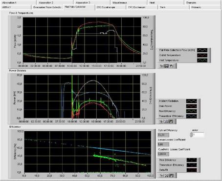
The next two tabs have the data corresponding to the solar collectors fields, the first for the evacuated tube collectors and the second for the flat plate ones. In each one of these tabs, there are three different charts (Fig 2):
The upper chart shows the evolution of the inlet and outlet temperatures as well as the flow throughout time.
The central chart shows the incident power on the field, estimated as the product of the radiation on the surface by the area. Here is also the power produced on the solar field. Using this previous data, with the quotient between them can be obtained the temporal evolution of the performance. Another represented curve is the theoretical performance that should be obtained on the field based on the manufacturer data.
In the chart of the bottom there is a comparison of the theoretical performance curve given by the manufacturer with the real one obtained from the collectors field. It is also made an estimation of the coefficients of the performance curve, using both lineal and quadratic approximation with the real performance curve.
 |
The next two tabs are related to the heat exchanger. On Fig 3 can be seen the behaviour of the heat exchanger of the flat collectors field. Again there are three charts: the upper one, shows the four temperatures and the two flows for primary and secondary along the time.
Fig 2. Trend charts for the Flat Collectors (31/08/2007)
Fig 3. Trend charts for the heat exchanger (31/0822007)
On the central chart, are shown the power on primary and secondary, and with it the instantaneous yield. Based on the temperature, it is determined la efficiency and the LMDT (Log Mean Temperature Difference). And finally the chart in the bottom represents the exchange coefficient, referred to the primary as well as to the secondary and the Capacity Coefficient.
The next tab is related to the storage tanks. It allows to see the evolution of temperatures on the top, bottom and middle of the tanks as well as the one in the room where them are situated. There has been designed two analogous charts, each one for one of the fields. By means of the difference between the values on the top and bottom of the tanks they can be represented the total stratification and the water temperature on the return of the installation. They are also shown the slope of each one of the curves. With this choosing a time period in which there is no activity on the tanks, the heat losses on each section can be estimated.
The next tab, called Hydraulic, shows the evolution of the pressures on the solar circuits. There are three charts. The one on he top, represents the flow on the solar primary and the looses of pressure of each one of the pumps, and this is used to calculate the hydraulic resistance throughout time. The central chart represents the pressure and la the hydraulic resistance, as a function of the flow. The lower chart represents the addition of the absolute pressure to the drop of pressure on the pumps.
On the second line of tabs the three first represent the evolution of the absorption chiller. The first shows the three basic circuits (Fig4): generator, evaporator and condenser. Each one of the charts contains the inlet and outlet temperatures, the flow and the power along the time whit regard to each circuit.
The second tab, (Fig 5) shows the evolution of the inlet and outlet temperatures on the loads circuit, as well as the demanded power. Also can be seen the evolution of the cold tank temperature and finally, the temperatures on the regulation valve of the condenser.
The third tab (Fig 6), represents the evolution of the temperatures on the generator valve. There is too a summarising chart with all the powers of the chiller. And finally, a chart with the COP using as a base the loads power or the evaporator power, as well as the load fractions for generator and evaporator.
 |
| Hidrauiic Energies
Fig 4. Absorption chiller’s generator, condenser and evaporator from 05:00 to 15:00 (13/08/2007)
 |
Fig 5: Absorption chiller’s load, cold storage and condenser valve from 05:00 to 15:00 (13/08/2007)
Fig 6. Generator valve, powers and performance from 05:00 to 15:00 (13/08/2007)
The next tab is Miscellaneus, in which two charts can be found: one with the more relevant operation temperatures and another with the averages calculated according to the methodology SACE [1]
The next tab, called Heat, shown a summary of the flows of the installation’s currents. Here can be seen the contributions that receives the absorption chiller and where do they come from: from the boiler or from the solar camp, and in this case, when is from the flat pate collectors, when from the evacuated tube collectors and when from both.
The last, shows the exploitation energetic balance for the installation during the calculation period established, in such way that can be seen for each one of the solar fields: energy incident, energy absorbed by the collectors, energy that reach the primary and the one that leaves the secondary on the heat exchangers, and accumulated energy. With all of those data, the calculation of the performance for collectors and heat exchangers is immediate. There is also done an estimation of the average powers using the working hours of each one of the circuits. Regarding to the chiller, is shown the energy of all of the four circuits (condenser, evaporator, generator and loads), the average powers during the working time and the average value of the temperatures SACE [1].
They are determined too the average COP using as a base the loads or the evaporator, as well as the solar fraction and the fractions for generator and evaporator.
To plan one installation, including a high level of instrumentation is fundamental in order to obtain enough information of the installation and its elements, being necessary as well to have tools to analyse it.
The program described in the present work, has made possible among others: to observe the evolution of the installation, detect malfunctioning, detect failures committed during the design and assembling of the installation and the identification of the different elements to be used on simulations.
For the future, it is expected to add new functionalities to the program, in order to obtain even more information.
[1] C. A. Balarasa, G. Grossmanb, H. M. Henningc, C. A. Infante, E. Podessere, L. Wangd, E. Wiemken,
Solar air conditioning in Europe—an overview, Renewable and Sustainable Energy Reviews, 11 (2007) 299-314
[2] J. Rodriguez, L. A. Bujedo, P. J. Martinez, Identification of real solar systems. Simulation parameters, ISES European Regional Conference, Eurosun’06, Glasgow, (2006).
[3] M. Poncela, J. I. Diaz, P. M. Caballero, L. A. Bujedo, Description del sistema de climatizacion solar por absorcion y de la red de monitorizacion y control del edificio de CARTIF. I Encuentro Iberoamericano de Refrigeracion y Aire Acondicionado, (2001)
[4] J. A. Duffie, W. A. Beckman, (1991). Solar engineering of thermal processes 2nd edition, John Wiley & Sons, New York.
A method has been developed at Uppsala University, Sweden, to generate hot water load profiles for households [5, 6]. The model aims at presenting the daily distribution of hot water demand between different individual households as well as average Swedish households based on peoples’ statements about their activities. The input to the model is time-use data from so called time diaries, and the model converts the activity data into hot water volumes and energy use. The material constituting the base of the model is a pilot study on time-use performed in the autumn of 1996 by Statistics Sweden, which was later coded at Linkoping University [8]. The households were selected by Statistics Sweden and the selection is assumed to be representative for Swedish households. It should be noted that the time-use study did not focus on energy use, but on time-use in general. Therefore, the participants are assumed not to have manipulated the time statements to look better from an energy perspective.
A total of 464 persons in 179 different households living in detached houses and apartments participated in the study. The participating household members filled in all the activities they performed, the duration of the activity as well as accompanying persons, among others in the time diaries. The diaries were recorded for one weekday and one weekend day, specified by Statistics Sweden, by all household members older than ten years. By connecting parameters describing the assumed type of tapping (extension in time and draw-off pattern) as well as the amount of hot water to
different activities a model was developed in the computer program Matlab. The hot water volumes for different activities as well as temperatures can easily be varied to suit possible known conditions.
The model output is hot water profiles in volumes or energy/power for individuals, households or groups of people, separated in apartments and single-family houses. Different time resolution can be chosen, from five minutes intervals, which is the time resolution mainly given in the time diaries, up to one hour. The model can also be applied to any time-use data organised similarly to the basic data set.
The liquid-side heat transfer correlation is valid for high Re numbers (see section 2.4). For the airside performance correlations used in the model, the validity range is determined by the range of heat exchanger geometrical parameters and operating parameters in the data base. These are (here shown only for dry surface):
For plain fins [10]: Reair = 300 — 11000, N = 1-6, Do = 6.35-12.7 mm, Fp= 1.19-8.7 mm, Pt= 17.7-31.75 mm, Pi = 12.4-27.5 mm.
For herringbone wavy fins [12]: Reair = not explicitly mentioned, but should be in a similar range as in the correlation above, N = 1-6, Dc = 7.66-16.85 mm, Pd = 0.3-1.8 mm, Fp= 1.21-6.43 mm, Pt= 21-38 mm, Pl = 12-33 mm.
Although a corrugation angle is one of the parameters in the correlation, its range is not given in
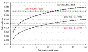
[12] . Additionally, wave height Pd or wave length xf are not considered in the correlation, although they have a considerable influence on heat transfer and friction coefficients at Re > Recritical [20]. Furthermore, the influence of the corrugation angle in the heat transfer correlation is inconsistent. For some geometrical parameter combinations heat transfer coefficient expressed in terms of Colburn factor increases with increasing corrugation angle as expected or stated by many investigations (cf. literature review in [20]), Fig. 1a. For other parameter combinations it does not, even having sometimes a clear optimum, Fig. 1b. Whereas the friction factor increases with increasing fin corrugation angle as expected, Fig. 2. Additionally, for some fin corrugation angle values the Colburn factor j and the friction factor f for wavy fins are smaller than those for plain fins (calculated according to [10]), Fig. 1 and 2. These effects are obviously caused by a complex structure of the correlation. Unfortunately, no other (“better”) correlations for wavy fin heat exchangers were identified in the literature, nor did Jacobi et al. [14] find any.
|
Table 1: Geometrical dimensions of the heat exchangers referred to in this paper.
|
 |
 |
Fig. 1. Influence of the fin corrugation angle on a Colburn factor j correlation [12] for two heat exchanger
configurations: (a) left HX 2, (b) right HX 3, see Table 1.
 |
 |
For comparison, values of the Colburn factor for plain fins [10] are also shown.
Fig. 2. Influence of the fin corrugation angle on a friction factor f correlation [12] for two heat exchanger
configurations: (a) left HX 2, (b) right HX 3, see Table 1.
All chosen airside correlations have similar accuracies. They describe about 90% of experimental heat transfer data (Colburn factor) and approx. 85% of friction factors within 15% error.
The flow friction usually contributes more than 90% of the airside pressure drop in a heat exchanger [18], so that the model accuracy regarding the airside pressure drop calculation is in a similar range as the accuracy of the airside friction factor correlation. An accuracy of equations for friction factor in tubes is not given in [19]. Thus, the model accuracy regarding the pressure drop calculation on liquid-side is unknown.
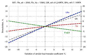
The heat transfer rate is not directly proportional to the airside heat transfer coefficient. Therefore, a differential sensitivity analysis was carried out in order to estimate the influence of the uncertainty of the airside heat transfer coefficient on the heat transfer rate. The results for the heat exchanger geometry HX1 (see Table 1) and two different ratios of UA values on liquid and air sides are shown in Fig. 3, where the airside heat transfer coefficient was varied up to 20%. The UAo value on the air side changes less than the Uo value, because the fin efficiency is negatively correlated with Uo. The overall UA value is less sensitive than UAo, but its sensitivity depends on the ratio of UAi and UAo. For both presented typical UAi and UAo ratios, the change in the heat transfer rate remains less than 5%, when the airside heat transfer coefficient varies within ±20%. Thus, the model accuracy regarding heat transfer calculation is within 5%, when the uncertainty of the airside heat transfer coefficient is less than 20% (at least for the investigated geometry).
 |
 |
Fig. 3 Heat transfer sensitivities on an airside heat transfer coefficient for geometry HX 1 and two different
ratios of UA values on liquid and air sides
Fig. 1. Sketch of the system simulated
This system with only a water store is used as the reference system for this study. More detailed information can be found in R. Heimrath and M. Haller [5].
The storage system used in these simulations has different modules of PCM inside the storage tank. To supply the DHW demand, the PCM modules are placed at the top part of the store. The PCM selected is a granular PCM-graphite compound of about 90 vol.% of sodium acetate trihydrate and 10 vol.% graphite.
The properties of this PCM, provided by the manufacturer, are a density of 1.35 kg/L, a melting point of 58°C, a heat capacity of 2.5 kJ/kg-K, an enthalpy of 180-200 kJ/kg, and a thermal conductivity of 2- 5W/m-K.
To supply the heating demand, the PCM modules are placed in the middle part of the tank from a relative high of 1/4 to 3/4, occupying half part of the tank. The PCM selected is a paraffin with a melting point of 48 °C. No more technical data is available.
The PCM simulated is placed into the storage tank in cylindrical modules. The amount of PCM into the store depends on the value of the filling ratio (Parea) and the length of the modules. The filling ratio (Parea) is defined as the cross-sectional area of all modules divided by the cross-sectional area of the storage. Three different values of the Parea ratio were simulated: 0.25, 0.5 and 0.75. When the PCM is added only for DHW supply, those ratios mean a PCM volume ranging from, approximately, 2% to 10% (depending on the module length); when the PCM is used to supply DHW and heating demand, the PCM ratio is from 8% to 25%.
 |
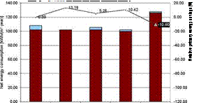 |
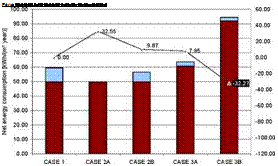
In this part, the auxiliaries consumption presented in paragraph 4.2 are not anymore taken into account. Net energy consumption and primary energy consumption are presented for different cases. Case 2A or 3A are related to a 3 floors building, case 2B or 3B to a 12 floors building. Figure 4 gives a diagram of heating and cooling energy consumption.
The system is modeled and simulated with TRNSYS and the typical meteorological year (TMY) of Nicosia, Cyprus. In this section both TRNSYS and TMY are shortly presented and details of the model are given.
3.1 TRNSYS Program Description
TRNSYS is an acronym for a “transient simulation program” and is a quasi-steady simulation model [3]. The program consists of many subroutines that model subsystem components. The mathematical models for the subsystem components are given in terms of their ordinary differential or algebraic equations. With a program such as TRNSYS, which has the capability of interconnecting system components in any desired manner, solving differential equations and facilitating information output, the entire problem of system simulation reduces to a problem of identifying all the components that comprise the particular system and connecting them together to form the complete system model.
The latest version of TRNSYS (version 16) works in a graphic interface environment called the simulation studio. In this environment, icons of readymade components are dragged and dropped from a list and connected together according to the real system configuration. Each icon represents the detailed program of each component of the system and requires a set of inputs (from other components or data files) and a set of constant parameters, which are specified by the user. Each component has its own set of output parameters, which can be saved in a file, plotted, or used as input in other components. Thus, once all the components of the system have been identified and as the mathematical description of each component is readily available, the user all he has to do is to construct an information flow diagram for the system, the purpose of which is to facilitate identification of the components and the flow of information between them. The flow diagram also contains information on the weather data file and the output format.
TRNSYS is employing the standard second-order collector performance equation to model the collector, given by:
(T — Ta) (T — Ta )2
where kaT is the incidence angle modifier given by:
The values of c0, cb c2 and bo are obtained by experimental testing of collectors in accredited laboratories. The values employed in the present system are shown in Table 1. The useful energy extracted from the collectors is given by:
ft = FAKtTG — ft ( — Г, )] (3)
The total useful energy for the whole year is obtained from:
365 24
![]()
Q„,a = YY. Q.
d=1 h=1
and the auxiliary energy required, Qaux is:
where Qload is the energy required by the load, Qloss is the energy lost from the storage tank and pipes and Qrei is the energy relieved from the storage tank relief valve.
As can be seen from the above equations the energy obtained from the solar collector field depends on the collector area (A), collector slope (affects cos0), flow rate (affects FR) and the storage tank size (affects Ti). The collector inlet temperature depends also on the load pattern, make-up water temperature, the losses from the storage tank and pipes and the energy relieved from the relief valve. The storage tank losses and energy relieved from relief valve depend on the temperature of the stored water, i. e., it depends on the energy collected and storage tank size.
The system presented in this paper is simulated with TRNSYS using Typical Meteorological Year (TMY) data for Nicosia, Cyprus. The selection of typical weather conditions for a given location is very crucial in computer simulations for performance predictions and has led various investigators either to run long periods of observational data or to select a particular year, which appears to be typical from several years of data. The TMY for Nicosia, Cyprus, was generated from hourly measurements, of solar irradiance (global and diffuse on horizontal surface), ambient temperature, wind speed and direction and humidity ratio, for a seven-year period, from 1986 to 1992 using the Filkenstein — Schafer statistical method [4]. The measurements were recorded by the Cyprus Meteorological Service at the Athalassa region, an area at the suburbs of the town of Nicosia. The TMY is considered as a representative year for the Cypriot environment.
TMY is defined as a year, which sums up all the climatic information characterizing a 30 year period record and not the operation lifetime of solar systems. Every about 10 years TMY files need updating to reflect climate changes, especially in cases where urbanization, pollution, increasing/decreasing of aerosols, drought, etc. takes place. Therefore an added advantage of the present method is that if this periodic updating of TMY fails to be done in regular intervals, some extreme effects can be accounted. Additionally, uncertainty in the weather patterns could include large-scale geophysical, human or nature caused events, like volcanic eruptions (Mt. Pinatubo eruption created aerosols which took two years to settle out), forest burning, increased storm occurrence, etc. which can have a much larger impact on short term and long-life system performance.
In this paper the effect of introducing uncertainty or noise in the weather data and load pattern is examined. The noise is introduced by using Type 578 (Random number generator). This model creates a random number drawn from a normal distribution based on user supplied values of the
mean (average) and standard deviation. For the parameters considered here these are shown in Table 3.
|
Table 3 Mean and standard deviation of the parameters considered in this work
|
It should be noted that higher values of radiation resulted in messages that the horizontal component of radiation is higher than the extraterrestrial value and that the latter will be used, as a maximum value.
For the ambient temperature the noisy value is added to the normal value using the equation component of TRNSYS as:
Ta, new Ta, normal + Ta, noisy (6)
For the case of solar radiation the following equation was used in order to avoid adding radiation in hours where the normal value is zero, i. e., during nighttime:
Radnew Radnormal+LT(0,Radnormal)*Radnoisy (7)
The term LT (0,Rad) is a standard TRNSYS function which returns 1 when Rad>0 and 0 when Rad=0. Similarly for the load demand:
DHW new=DHW normal+DHW noisy*LT(0,DHW normal) ( 8 )
This avoids adding demand at the hours where its value is zero (early in the morning, see Fig. 2).
It should be noted that this analysis could also be performed by specifying the mean or average values of the various parameters shown in Table 3, without the need of equations (6) to (8). In this case however, the introduction of negative values into the simulation would have been unavoidable.
3.2 System Simulation
The normal system simulation is carried out with the aid of TRNSYS and the TMY for Nicosia, Cyprus. The system is also simulated by introducing noise in various parameters as shown above.
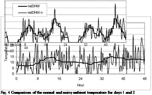
In all graphs that follow the mark “n” in the various parameters represent the values corresponding to the operation with noisy conditions. Figures 3 and 4 show a comparison of the normal and noisy radiation and ambient temperature respectively as obtained from the program for the first two days of the year. Similarly, Fig. 5 show a comparison of the normal and noisy hot water consumption profile for the same period. As can be seen the radiation values are not affected significantly whereas both ambient temperature and demand profile show large variations. It can also be seen that the noise is different from day to day, it is however impractical to show this variation for all days of the year.
A comparison of the annual performance of the normal (without noise) and noisy systems is shown in Table 4. As can be seen the annual differences are minimal which means that the noise introduced as described above has not created large differences. The solar energy incident on the
 |
collector is very much the same whereas the greatest difference is for the auxiliary energy which for the noisy system is reduced by 6.3%.
Fig. 5 Comparison of the normal and noisy hot water consumption profile for days 1 and 2
Of course the differences on a daily basis are expected to be more significant and these are presented and analyzed below. As it is impractical to show a comparison for all months of the year only January and July are presented showing typical winter and summer performance respectively.
 |
|
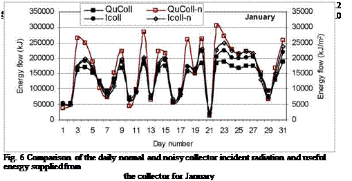
As can be seen from Figs. 6 and 8, in both January and July, although the difference in the total radiation falling on the collector is not much there is considerable difference in the useful energy supplied from solar collectors.
|
January A jy’AsA’^A. a. Ay |
||
|
1 |
3 5 7 9 11 13 15 17 19 21 23 25 27 29 31 Day number |
|
250000 200000 150000 |
|
Fig. 7 Comparison of the daily normal and noisy domestic hot water load and auxiliary energy supplied from the collector for January |
Also as shown in Figs. 7 and 9 for January and July respectively, the hot water load for the nonnoisy case is almost constant and much larger for the noisy case, but this has almost a negligible effect on the auxiliary energy required during the summer period and a more pronounced effect during the winter, as both the makeup water temperature replacing the demand and the performance of the solar system during this period are much lower.
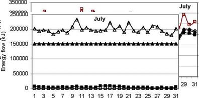 |
Fig. 9 Comparison of the daily normal and noisy domestic hot water load and auxiliary energy supplied from
the collector for July
2. CONCLUSIONS
As it is proved in this paper annual performance of the system is not very much different compared to the normal non-noisy model whereas the daily and hourly performance shows some considerable variations. It is believed that the present method gives more reliable results to the long-term performance evaluation of the systems and should be followed once the optimum system is obtained as it produces more reliable results. This is more important in cases where guaranteed solar results schemes are followed where possible mistakes could result in significant penalties.
References
[1] Kalogirou, S., The potential of solar industrial process heat applications, Applied Energy, 76 (2003) 337-361.
[2] Kalogirou, S., Optimisation of solar systems using artificial neural networks and genetic algorithms, Applied Energy, 77 (2004) 383-405.
[3] Klein S. A., et al. (2004) TRNSYS program manual, University of Wisconsin.
[4] Kalogirou, S., Generation of typical meteorological year (TMY-2) for Nicosia, Cyprus, Renewable Energy,
28 (2003) 2317-2334.
G. Steinmaurer
ASiC — Austria Solar Innovation Center, A — 4600 Wels, Roseggerstrasse 12, Austria.
Abstract
In Wels, Austria, an existing district heating grid with a fossil main heat source and a thermal storage tank will be extended by a solar thermal feed-in. The combination of an existing heat source, a solar thermal plant and a thermal storage tank makes it necessary to develop a ‘load management’ as a fundamental component, which coordinates the energy distribution by using optimization methods and solar radiation forecast. To asses the possibilities and the capability of the load management it was necessary to design an appropriate simulation environment within the well known dynamical simulation software Matlab/Simulink and the Carnot-Blockset. The use of this simulation environment makes it necessary to built up new components, which has not been included so far in the Software-library. To evaluate the validity of new parts, system identification methods and parameter estimation procedures have been implemented.
Keywords: solar thermal power plant, energy management, energy coordination, optimal power flow, Matlab, Simulink, Carnot-Blockset.
In Wels, Upper Austria, an existing district heating grid with a fossil main heat source and a thermal storage tank will be extended by a solar thermal feed-in. By considering the economic efficient operation of the overall system, the energy-efficient integration of the solar thermal plant (approx. 3.700m2) has to be investigated particularly [1]. The existence of different energy sources (the heat source and the solar thermal plant) and the possibility to store energy in a thermal storage tank produces the necessity of a so called “load management”. This essential component coordinates and distributes the thermal energy within the overall plant.
The load management system is developed using optimization methods and includes additionally solar radiation forecast to estimate the heat demand of the district heating grid as well as the expected solar thermal power.
For kindergarten operation there are available monitored data that we can expect to approximate by calculations the changing of the studied variables, for example solar storage temperature, within a few percentages accuracy. Comparison of the calculation by the physically-based model and the measurements is shown to this case thereinafter.
Both for the swimming pool and for the kindergarten models there are parameters of which the exact values are not known, they must be determined somehow. Such parameters are the optical efficiency (no) and the overall heat loss coefficient (UL) of the collector in the collector sub-model, the ke coefficient of the heat exchanger in the heat exchanger sub-model, the heat loss coefficient (ks) and the surface area (As) of the wall of the solar storage tank in the solar storage sub-model.
Given values for the calculations are as follows:
П0 = 0,74, catalog data for the SlU-system,
UL = 7 W/(m2K), recommendation from [9],
ke = 2461,5 W(m2K), determined from data given by manufacturer, ks = 0, assuming storage with no heat loss.
Since the storage has no heat loss the value of As is of no interest.
In accordance with Fig. 3 the temperature of the solar storage has been determined for two independent day (8 March, 2005, 8 April, 2005), by running the model with available measured data. Fig. 4 and Fig. 5 contain the comparison of the calculated and the measured values, as well.
|
Fig. 4. Comparison of storage temperatures for 8 March, 2005. |
As a result of the modelling the absolute difference of the calculated solar storage — and the measured solar storage outlet temperature has a mean value of 1,11°C, standard deviation of 0,6°C, maximum value of 2,32°C and residual value of 0,51°C for the day 8th of March, 2005.
|
Fig. 5. Comparison of storage temperatures for 8 April, 2005. |
As a result of the modelling the absolute difference of the calculated solar storage — and the measured solar storage outlet temperature has a mean value of 0,73°C, standard deviation of 0,49°C, maximum value of 1,78°C and residual value of 0,69°C for the day 8th of April, 2005.
The following information was identified, collected and analyzed: potential of solar, aeolic and biomass resource, socio-economic information, geographic maps, infrastructure data, hydric resources (subterranean wells), soils and climatic aptitude, possible nuclei for becoming training and technical assistance centers (technical and agricultural schools, universities),and finally mapping of existent solar installations. The data used where possible, were automatically migrated, if not were digited and converted in ACESS data bank.
Acknowledgements — We thank the National Research Council (CNPq) , Brazilian Electric Centers SA (ELETROBRAS), The Sao Francisco Hydro Eletric Company (CHESF)and Coordination for Perfection of High Level Personnel (CAPES) for the aid in research projects on solar energy that provided material means and scientific ambient for carrying out this research.
[1] Bravo, J. D. (2002) Los sistemas de information geografica em la planificacion e integration de enrgias renovables, ISBN 84-7834-434-9, Editorial CIEMAT, Madrid, Espana.
[2] Bourges, D. et al. (1996) A geographical information system for large scale integration of renewable energies into regional energy markets, Renewable Energy Development European Conference and APAS — RENA Contractors Meeting, EDIFIR, Florencia.
[3] Rialhe, A. (1996) Epure project: economical potential use of renewable energy, Renewable Energy Development European Conference and APAS-RENA Contractors Meeting, EDIFIR, Florencia.
[4] Diakoulaki, D. et al. (1996) Implementing large scale integration of renewable a pilot study for operational plans and policies (REPLAN), 107-115.
[5] Voivontas, D., Assimacopoulos, D. and Mourelatos, A. ( 1998) Evaluation of renewable energy potential using a GIS decision support system, Renewable energy, Vol. 13, No. 3, 333-344.
[6] Petit, C. (1995) Winds of change. GIS helps site wind farms in France. GIS Europe, Godmanchester (Huntington), GeoTec media, pags. XVII-XVIII.
[7] Baban, S. M. J. and Parry, T. (2001) Developing and applying a GIS-assisted approach to locating wind farms in the UK, Renewable Energy, Vol. 24, No. 1, 59-71.
[8] Matthies, H. et al. (1994) An assessment of the offshore wind potential in the EC, EWEC94, Greece,
111- 115.
[9] Marnay, C. H. et al. (1997) Estimating the environmental and economics effects of widespread residential PV adoption using GIS and NEMS, Ernest Lawrence Berkeley National Laboratory,
University of California, EEUU Report, LBNL-41030, UC-1321.
[10] Noon, C. H. and Daly, M. J. (1996) GIS-based biomass resource assessment with BRAVO, Biomass and Bioenergy, Vol. 10, No. 2-3, 101-109.
[11] Voivontas, D. et al. (2001) Assessment of biomass potential for power production: a GIS based method, Biomass and Bioenergy, Vol. 20, 101-112.
[12] IBERINCO(1998) Oportunidades para la production de energia a partir de biomasa en La Rioja (Espana) y La Toscana (Italia), ALTENER pilot projects, Contract No. XVII/4, 1030/Z/98-214.
[13] SOLARGIS TEAM (1996) Solargis handbook, Comision Europea, Direction General XII, Bruselas.
[14] NREL (2007), Dynamic maps, GIS data and analysis tools, www. nrel. gov/gis/maps
[15] RENEWABLE ENERGY ATLAS OF THE WEST (2007), www. energyatlas. org, 2007.
[16] Suri, M. Huld, T. A. and Dunlop, E. D. (2005) PV_GIS: a web-based solar radiation database for the calculation of PV potential in Europe, Int. Journal of Sustainable Energy, Vol. 24, No. 2, 55-67.