Как выбрать гостиницу для кошек
14 декабря, 2021
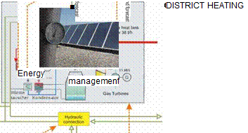
The combination of an existing heat source, a solar thermal plant and a thermal storage tank makes it necessary to develop an ‘energy management’ as a fundamental component (Fig. 3). This energy coordination has to guarantee, that
• The overall system operates in economic efficient way, i. e. a minimum of fuel is used to meet the demand of the district heating grid
• Boundary conditions will be fulfilled. These general conditions are e. g. physical limits of the storage tank or the combined gas and steam cogeneration plant.
 |
|
The necessary heat supply of the cogeneration plant can be calculated at any time instant from the heat demand of the heating grid, reduced by the actual power of the solar thermal plant and the contribution of the storage unit (which can be either positive or negative — depending on charging or discharging operation of the storage tank). Changing the contribution of the storage unit results in a changed operating point of the cogeneration plant and it associated degree of efficiency.
Fig. 3: Structure of the solar assisted district heating grid
The energy management has then to decide, if — at a certain heat demand — the storage tank has to be charged or discharged. This decision is based not only on actual values of the overall system but can also depend on future assumption of the plant behaviour. That means e. g., that the storage tank is not
charged, if the solar thermal plant can provide enough energy to the district heating grid in the next hours. To predict such an event, a weather forecast has to be implemented in the energy management tool. Since the heat demand is correlated strongly with the weather conditions, the weather forecast can also be used to predict the heat demand.
The concept of such an energy coordination unit is typically based on an enormous number of ‘lingustic’ rules, like
• “… if the heat demand is low, the ‘state of charge’ of the storage tank is low and the temperature forecast predicts 15°C in the next hour, then storage unit is charged with 780 kW heat power…”
Within this project, a different approach for the design of the energy management was used. It is based on an analytical procedure [2, 3], where the development of the energy coordination unit is the result of an optimization task
T
min [ ф(и(т),…)ёт = min^ф(ик,…)
u (t) uk
s. t. boundary conditions are fulfilled,
where ф(-) is the instantaneous fuel consumption of the cogeneration plant and u(t) represents the charging/discharging level of the thermal storage tank. Boundary conditions have to guarantee, that the storage tank is not overcharged of discharged completely.
The basic principle of the ‘load management’ and the development of the underlying mathematical methods have been shown in [2]. The used optimization horizon was set to 1 year. Since one can not know exactly the weather conditions and solar radiation for such a long forecasting horizon, the optimization problem was split up into two tasks
• The long-term scheduling problem (with assumed average values within the optimization horizon) and
• The short-term scheduling problem (works as a correction of the long-term problem with actual values).
For the comparison the geometry of the greenhouse-environment system shown in figure 1 was taken into consideration.
|
Fig. 1. Sunspace-environment system and schematization of solar heat gains. Te external air temperature, Ta air temperature in the airconditioned environments, Ts air temperature in the sunspace. |
The sunspace, measuring 6^3×3 m in dimension, borders with the outside by means of three vertical walls and the roof, and is separated from the airconditioned environment by a wall that is part glazed and part opaque; furthermore it borders with an underlying environment that is also airconditioned. The glazed surfaces are formed by a clear double glass 4-12-4 with thermal transmittance Ug = 2,88 W/m2K and solar gain coefficient gi = 0,747. The internal opaque wall and the floor of the sunspace have a respective thermal transmittance of Uw = 0,55 W/m2K and Uf= 0,57 W/m2K. The other walls of the airconditioned environments are considered internal walls, adiabatic in corrispondence with the symmetry axis.
The overall heat transfer coefficients by ventilation between the greenhouse and the outside, and between the airconditioned environment and the greenhouse were placed equal to 18 W/K and correspond to an air change equal to 1 volume/h. The coefficient of surface thermal exchange of the sunspace floor hf was set equal to 10 W/(m2K) and that of the opaque dividing wall hw = 7,7 W/m2K [7]. In the evaluation of the thermal coupling coefficient between the airconditioned volumes and the sunspace, through the vertical wall and the floor, the effects of thermal bridges were not taken into consideration. Furthermore for the glazed surfaces corrective factors due to shading, to curtains and to the frame were considered unitary.
With reference to figure 1, the total solar contribution through the vertical separation wall QW and through the greenhouse floor Qf were obtained by adding the respective direct Qd and indirect Qt contributions
Qw = Qd, g + Qd, w + Q w (1)
Qf = Qd, f + Qf (2)
Indirect contributions require the evaluation of the net energy absorbed by the sunspace Qa
Qa = Qw + QaJ — Qd, w — Qdf (3)
and are calculable with the relations
with Hw and H f heat loss coefficients between the airconditioned spaces and the greenhouse, through the mixed vertical wall and the floor, and He loss coefficient between the greenhouse and the external environment [8].
With the considered outlined conditions, the average monthly temperature within the greenhouse is given by the relation
![]() Qa
Qa
(Hw + Hf + He )At
with Ta the temperature of the adjacent airconditioned environments, set at 20°C during the heating period and at 26°C during the cooling period, and At the number of seconds in a month.
With reference to two Italian localities characterised by different climatic conditions, Milan (Lat. 45°27’, Long 9°11’) and Cosenza (Lat. 39°18’, Long 16°15’), direct, indirect and global solar contributions were compared with a variation: of the glass fraction f of the greenhouse — environment separating wall f = 20%, 60%, 100%); of the orientation of the greenhouse (South, East, West); of the optical properties of the opaque surfaces, the absorption coefficient of the solar band was presumed to be identical for the different surfaces of the greenhouse and the environment, and was made to vary between a=0,2 (highly reflecting environment) and a=0,5 (moderately absorbing environment). Furthermore, the solar contribution obtained in the airconditioned environment in the absence and presence of the greenhouse was evaluated.
 |
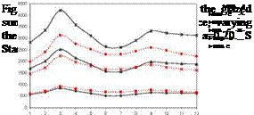 |
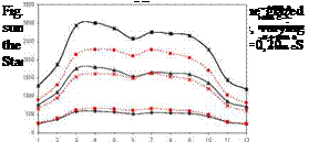
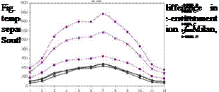
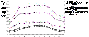
The monthly direct, indirect and total solar heat gain, through the separation wall and the floor obtained with the simulation code and the Standard were compared. The direct contribution through the glazed surface for Milan and Cosenza, with a variation of the glass fraction f, for a = 0,20 and for its Southern exposure are reported in figures 2 and 3.
The results of the comparison depend on the glass fraction, in particular for glass fractions of 20% the Standard underestimates with greater deviation in the summer period (23% for Cosenza, 17% for Milan) and is more contained during winter months (less than 10%). Instead, for 100% solar fractions, the Standard leads to a significant overestimation in winter months for both locations, with deviations of 43%. During summer months such a percentage is reduced to 13% for Cosenza and to 20% for Milan. For Eastern exposure, the previous trends remain confirmed with reduced deviations which do not exceed 17% for f = 20%, and 33% for f = 100%. For an absorption coefficient value of the greenhouse-environment system equal to 0,50, the Standard provides evaluation in good agreement with the code, with deviations which does not exceed 17%.
 |
 |
 |
|
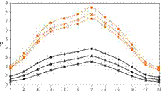
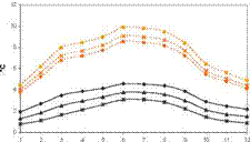
For the comparison of the indirect contribution through the separation elements between the greenhouse and the airconditioned environments, the comparison of the temperature increase of the air within the sunspace is significant, as a consequence of solar absorption and exchange through the shell. In figures 4 and 5, for Milan and Cosenza, the monthly trends of the increase in temperature in the greenhouse relative to its Southern exposure are reported for environments with a = 0,20.
Fig. 4. Increase in sunspace air temperature 4 Fig. 5. Increase in sunspace air temperature consequent to consequent to solar absorption, varying the glass 4 solar absorption, varying the glass fraction f. Cosenza, fractionf. Milan, South, a=0,20. S Standard, C code. South, a=0,20. S Standard, C code.
The Standard underestimates the increase in temperature with variations between 1,0 °C in January and 4,5°C in July for Milan, and between 2,5°C and 5,3°C for Cosenza, for the different glass fractions. The increase in the absorption coefficient (a = 0,50) gave rise to a more contained underestimation of the increases, with deviations that for Milan do not exceed 3,0°C in July for f= 100%, and 3,7°C for Cosenza. For Eastern exposure similar variances were found.
 |
 |
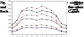
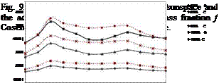
The solar heat gains obtained as the sum of direct contribution through the opaque surfaces and the indirect contributions consequent to the heating of the greenhouse, evaluated with the Standard, are compared with the contributions in the environment adjacent through the separation wall, evaluated with the code. It can be observed that the Standard gives rise to a systematic underestimation of such contributions. In figures 6 and 7 the values of the previous contributions for a = 0,20, southern exposure, for the considered localities are reported.
The Standard provides trends which vary slightly with the glass fraction, since, with an increase in the glass surface, the thermal coupling coefficient between the greenhouse and the adjacent environment increases while the energy absorbed by the opaque walls diminishes as demonstrated by the equation (4). Significant variations produced by the different evaluations of the increase in temperature between the greenhouse and the environment are highlighted, which increase with the glass fraction and are between 33% (f = 20%) and 84% (f = 100%) inclusive. For more absorbent environments, it is ascertainable that for contained glass fractions, the Standard gives rise to an overestimation, attributable to the evaluation of the direct contribution through the opaque wall, with deviations varying between 10% and 33%. Instead, for glass fractions f = 100%, the Standard leads to an underestimation with deviations between 23% and 55% inclusive. For Eastern exposure, similar trends are recorded with more contained deviations. The comparison of the contributions through the sunspace floor leads to considerations similar to the previous ones, in particular for a = 0,20 the Standard underestimates in a proportion increasing with the glass fraction, with variations between 24% and 58% inclusive.
For a = 0,50 the Standard overestimates in the summer months and underestimates in the winter months with deviations that do not exceed 24%. Finally, the comparison of total solar heat gains for the adjacent environment, the sum of the direct and indirect contributions, is reported for case a=0,20 and for Southern exposure in figures 8 and 9. For such configurations, the Standard underestimates the solar contribution with deviations which diminish with the increase of the glass fraction, and do not exceed 28%. Fore more absorbent environments and reduced glass fractions (a=0,50 ed f=20%), for both the localities the Standard underestimates the contribution in a measure less than 18%, while for the glass fractions it is higher (60%, 100%) [9].
 |
 |
The results provided by the two calculation procedures appear to be in agreement, as an effect of the compensation between the underestimation of indirect contributions and the overestimation of direct contributions.
In light of the simplifications hypothesised by EN ISO 13790, the results obtained with the code were used for quantitative evaluations on the direct and indirect solar heat gains for the adjacent airconditioned environment. Furthermore, the solar contribution of the sunspace — environment system obtained with the code was compared with those calculated by applying the Standard to the environment lacking a greenhouse in front of it.
 |
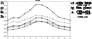 |
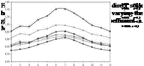
The indirect contribution was generally lower than the direct contribution, but they can also result as being greater in the case of absorbent environments with reduced glass fractions. Their relationship is a function of the glass fraction, of the absorption coefficient of the spaces, of the exposure and of the locality. In figures 10 and 11 the results obtained for Southern exposure for Milan and Cosenza are reported.
It should be immediately highlighted that the indirect contributions are not negligible in any case compared to the direct contributions, even when the increases in the temperature of the greenhouse are modest. With the same glass fractions, the indirect solar heat gain increases in a significant manner with the absorption coefficient since, in comparison with a modest increase of the direct contribution, the indirect contribution increases in a considerable way due to the greater absorption of the sunspace. It should be highlighted that the greater total contribution is obtained by configurations which ensure maximum direct and indirect solar heat gain, with prevalence over
direct contribution (f=100%). The previous trends with a lesser monthly variability remain confirmed for Eastern exposure.
In figures 12 and 13 the total solar heat gains for the sunspace-environment system, with a = 0,20 and Southern exposure, calculated with the code are compared with those evaluated by the Standard for the same windowed environment.
In Milan the sunspace gives rise to increases in contributions that, for a glass fraction of 20%, result as being hardly variable with the absorption coefficient and being between 25% and 35% inclusive during summer and between 11% and 19% during winter.
For Cosenza the percentages are between 21%-43% during summer, and between 12%-20% during winter. If the glass fraction increases, the solar contributions undergo variations during winter which differ to those during summer. In particular, during the winter months the presence of the sunspace gives rise to a reduction of the contributions, which results as being less than 17% for f = 60%, and less than 49% for f = 100%. The reduction of the direct solar heat gains linked to the presence of the greenhouse does not appear to be compensated by the indirect contributions.
 |
During summer, viceversa, the greenhouse determines an increase in contributions which do not exceed 21%. For environments which are more absorbent the previous variances undergo an attenuation during winter, while during summer they remain substantially unaltered. For Eastern exposure, poor monthly variability was observed for f = 20%, with values between 24% and 31% inclusive for both the localities and optical configurations. For higher glass fractions an invariance in solar contribution in the case of f = 60% was observed, and a significant reduction for f = 100% that is equal to 28% for Milan and a = 0,20. More contained variations were recorded for Cosenza.
Fig. 13. Solar heat gain for sunspace-adjacent environment systems and for windowed environments, varying the glass fraction f. Cosenza, South, a=0,20.
For a system comprising of a sunspace bordering airconditioned environments, the solar heat gain calculated by the simplified calculation procedure of the EN ISO 13790 Standard was compared with those obtained by means of a dynamic calculation code that accurately calculates the interaction between solar radiation and the glazed spaces adjacent to airconditioned rooms. The analysis, carried out for different climatic conditions, geometries and optical configurations, permitted the evaluation of direct solar contribution, through glazed and opaque surfaces, and indirect due to heating of the greenhouse, and the total contributions.
The different modelling of the absorption of solar radiation leads to different increases in air temperature in the greenhouse which lead to considerable underestimation of the indirect contributions on behalf of the Standard. For configurations with a solar fraction of 100% the variances reach 80%. Furthermore, it is possible to observe that, for such configurations, the direct contributions result as being overestimated by 40%. With regards to total contributions, the results provided by the two calculation procedures appear to be in greater agreement: deviations of less
than 28% are recorded for environments with a = 0,20 and lower than 18% for more absorbent environments.
With the aim of evaluating applicability, for the climatic conditions considered, the simplified hypothesis proposed by EN ISO 13790 (do not compute the indirect contributions, ignore the presence of a glass shell) the direct and indirect contributions obtained with the code were compared, and the solar heat gain for a windowed environment was calculated with the Standard. The indirect solar contributions, compared to direct contributions, result as being significant in percentage and variable according to the locality, the glass fraction, the absorption coefficient of the environments and the exposure. Therefore, the indirect contributions are in no case negligible even in the presence of contained increases in the sunspace temperature.
To the South, for reduced glass fractions (f=20%), the greenhouse gives rise to an increase in solar heat gain that is more accentuated in summer, and which reaches 35% for Milan and 43% for Cosenza. For greater glass fractions the greenhouse leads to a reduction in solar gain in winter, for f=100% it results as being equal to 49%, and increases of less than 21% during summer. For Eastern exposure the effects of the greenhouse appear to be more contained, for f=100% the increase of solar contribution does not exceed 31% for both localities.
[1] De Simone M. , Oliveti G. , Ruffolo S. , " EVALUATION OF THE ABSORPTION COEFFICIENT FOR SOLAR RADIATION IN SUNSPACES AND WINDOWED ROOMS". Solar Energy, Vol. 82, pp. 212-219, 2008.
[2] EN ISO 13790. Energy performance of buildings. Calculation of energy use for space heating and cooling, 2008.
[3] UNI EN 832. Thermal performance of buildings. Calculation of energy use for heating. Residential buildings, 2001.
[4] DEROB-LTH v1.0. User’s Manual. Division of Energy and Building Design, Lund Institute of Technology, Sweden, 2004.
[5] Arumi-Noe, F. The DEROB System, Volume II, Explanatory Notes and Theory. Numerical Simulation Laboratoty, School of Architecture, University of Texas Austin, 1979.
[6] UNI 10349. Heating and cooling of buildings. Climatic data, 1994.
[7] UNI EN ISO 6946. Building components and building elements. Thermal resistance and thermal transmittance, 1999.
[8] EN ISO 13789.Thermal performance of buildings. Transmission and ventilation heat transfer coefficients. Calculation method, 2007.
[9] De Simone M. , Oliveti G. , Arcuri N. , Bruno R. , " RADIAZIONE SOLARE NEGLI AMBIENTI ADIACENTI A SPAZI SOLEGGIATI. UNA VERIFICA DELLA PROCEDURA DI CALCOLO PREVISTA DALLA NORMATIVA". Book proceedings of the "46° International Conference AICARR", Milan, Vol. I, pp. 1009-1023, 12-13 March, 2008.
The default functionalities of the SIGA SOL 1.0, management module (PV management) are made up of three levels: a macro-spatial where the basic unit is the state, another local at municipal level and finally the possibility of updating of table data, according to what can be seen in Fig. 2.
It is well known, that the primary deficiency of polymeric materials with regard to their usage in solar collectors is their poor heat conduction. However, the heat conductivity A is not the only quantity that determines the heat transfer Q from the polymeric absorber surface to the fluid medium. From the formula of the heat transfer
![]()

 |
|
1
1 d T
+ +
a1 A a2
it becomes obvious that the heat transfer induced by convection (the a’s) is at least as important. This heat transfer is determined by the exact fluid behavior at the contact surface and in turn the fluid behavior depends on the geometrical shape of the surface. Since polymeric materials can be given almost any form the question arises if it is possible to optimize the shape of a polymeric absorber surface so that the heat transfer by convection overcomes the lack of heat conductivity.
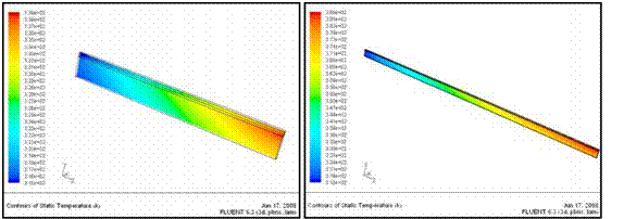
In this paper a first attempt towards optimizing polymeric collector surfaces is presented. Several CFD simulations were carried out for different geometries of the absorber. To illustrate the approach two of the candidate forms are considered (Fig. 3).
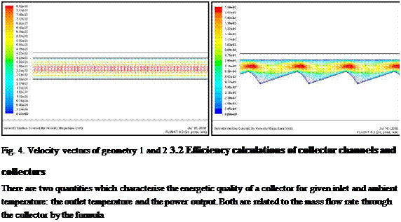
Computations of the fluid dynamics within these two models were made where the carrier fluid was water and the mass flow rate ranged from 10 to 40 kg/m2h. They resulted in identical final outlet temperatures and final power for the two shapes. Fig. 4 illustrates the velocity distributions in the chosen geometries.
This outcome is not really astonishing since the Reynolds numbers for all geometries are extremely low (Re<1) when the flow rates of water remain in the range mentioned above. This means that
 |
changing the geometry of the absorber alone will not lead to significant enhancement of the power of water driven collectors. However this goal could be achieved if the Reynolds number will be increased by operating at much higher inflow velocities and / or by using other carrier fluids than water. Such systems are currently under investigation.
![]() Q = Фm Cp AT.
Q = Фm Cp AT.
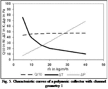 Values for all these quantities can be obtained from the results of the CFD simulations. The numerical studies showed a nonlinear behavior of both the outlet temperature and the power. In Fig.
5 AT and Q are plotted over the mass flow rate. The resulting curves can be interpreted as characteristics that allow comparing different collectors.
The graph shows clearly that there is a trade-off between the two parameters that matter with regard to quality of the collector. These plots can help to choose the collector with the maximum power given a desired working point (e. g.
given outlet temperature). On the other side the diagram shows how the operating conditions for high flow and low flow collector systems differ.
The results of a simulation are the effective transmittance-absorptance products under the specified angles of incidence and directions. Every particular IAM value of each measuring point of the hemisphere equals the relation of absorbed power under the corresponding incidence angle and direction to the one in case of perpendicular incident radiation.
It should be mentioned that the definition of the IAM as described in EN 12975 is used. This is different to the way as the IAM of concentrating collectors such as parabolic trough collectors is defined, where the IAM is based on the direct normal irradiation (DNI).
Figure 4 shows the simulation results for an evacuated tube collector with ten tubes, each with an outer diameter of 58 mm. The diagram indicates the values of the simulated collector for a quarter of the hemisphere. The values were calculated for incidence directions defined in polar coordinates (0 — theta, ф — phi). The determined 3D-IAM-values then were reassigned to the projected longitudinal and transversal components (0t — theta_t, 0l — theta_l), respectively, in order to depict them more clearly.
 |
There was build a mesh over the simulated points (red globes) seen in Figure 4 to display the 3D — IAM-values. The accuracy of the generated mesh depends on the distance of the simulated points to each other. It is advantageous to use the second possibility to simulate the 3D-IAM, using the projected longitudinal and transversal components (0t — theta_t, 0l — theta_l). It leads to a better resolution and the IAM-values are determined directly in the way as they are needed in TRNSYS. The result of this kind of 3D-simulation is shown in Figure 5.
The temperature field of the liquid flowing in a tube is described by the following equation [4, 5,
7]:
![]() DT3 = A V2T
DT3 = A V2T
c = A)V T3 dt
The Laplacian in a system of cylindrical coordinates is:
Equation (20) in cylindrical coordinates is expressed as
In conformity with Newton’s law, on the contact surface between the tube and the liquid (r= r0) the following equality holds:
![]() = — a(T3 — T2 ), d r
= — a(T3 — T2 ), d r
where a is the coefficient of convective heat transfer on the surface, W/m2K.
At the fixed points of the tube y = 0 and y = y1 we will determine the temperature as
T3(г, ф,0) = -3,0 ; Тз(г, ф,y) = Тзд. (23)
Having passed in Eq. (21) and boundary conditions (22), (23) to dimensionless variables (6)-(9), we obtain:
|
In order to solve the problem (24)-(26), function ©3 (р, ф,п) is divided to the components [6, 10]:
By Fourier’s method of separation of variables [6], using boundary conditions (31) one obtains: |
By Fourier’s method of separation of variables [8], using boundary conditions (32) and (33) we obtain:
![]() Pe_
Pe_
®{()(P, P,rl) = e 2 2 C022Jk(imp)shpmn +
m=1
+ e 2 7 ІІ C(l cos к (p — (Pmp)shPmV,
 |
|
k=1m=1 V 2 J
The calculations show that in the function describing the temperature field in the plate section O1ABC (17) the temperature is directly proportional to the solar energy density q, which could be expected since the greater the energy density the greater the temperature in the solar collector. The plate thickness is inversely proportional to the temperature, which means that the smaller the plate thickness the greater the temperature in the plate; however, if we decrease the plate thickness the angle ф will be smaller, which means smaller heat flow on chord BC — the main way through which the heat is flowing from the plate to the tube’s coating (31) and further to the liquid in this tube. Considering the temperature function (17) it can be concluded that the smaller distance b between tubes the greater the temperature in the plate; this, however, reduces the area irradiated by sun rays, which would mean that the collector is more inertial. Even such simple reasoning about the collector’s parameters allows for the conclusion that the mathematical description presented here can help to find the optimal sizes for the absorber, which, taken for the whole collector, would provide its maximum efficiency [2,3].
[1] P. Shipkovs, G. Kashkarova, K. Lebedeva, J. Shipkovs, M. Vanags, K. Leitans. “The mathematical description for heat conduction process on the surface of a solar collector’s absorber”. World Renewabe Energy Congress IX, Florence, Italy, 2006, CD Full Proceedings, 5 pp.
[2] P. Shipkovs, T. Esbensen, G. Kashkarova, K. Lebedeva, J. Shipkovs. Solar energy use in Latvian conditions. Journal of applied research official journal of Lithuanian Applied Sciences Academy, Lithuania, 2005,
Nr. 2, 68-73 pp.
[3] P. Shipkovs, G. Kashkarova, K. Lebedeva, J. Shipkovs. Prespectives for solar termal energy in Baltic states. Solar World Congress 2005, Orlando, Florida, USA, August 8-12, 2005, CD proceedings, 6 pp.
[4] Исаченко В. П., Осипова В. А., Сукомел А. С. (1969) Теплопередача Москва: Энергия 724 стр. (In Russian).
[5] Лыков А. В. (1972) Тепломассообмен Москва: Энергия 560 стр. . (In Russian)
[6] Будак Б. М., Самарский А. А., Тихонов А. Н. (1972) Сборник задач по математи-ческой физике Москва: Наука 688 стр. (In Russian).
[7] Лыков А. В. (1967) Теория теплопроводности Москва: Высшая школа 600 стр. (In Russian).
[8] Riekstins E.(1969) Matematiskas fizikas metodes Riga: Zvaigzne 620 lpp. (In Latvian).
 |
 |
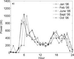
To investigate the daily distribution of hot water during different periods of the year, the measured average hourly hot water use for five months 2006 is shown in Figure 5. The curves coincide rather well, showing the same, typical variations. This implies that the individual behaviour is similar all year around. There is a difference between winter time and summer time found in Figure 4. In the winter months, January and February, the morning peaks appear somewhat later, especially in weekdays. According to the residential company, summer time is however accounted for in the measurements.
Figure 5. The figure shows the daily distribution of hot water use for different months. In figure a) an average
weekday is shown and in b) an average weekend day is found.
C. Garnier, J. I. Currie* and T. Muneer
Napier University, Scottish Energy Centre, 10 Colinton Road, Edinburgh AH10 5DT, UK
* Corresponding Author, j. currie@napier. ac. uk scientific. comm@eurosun2008.org
Abstract
A simple low cost integrated collector storage solar water heater (ICS-SWH) which has the potential to substantially reduce domestic energy use was proposed for simulation. The system takes the form of a rectangular-shape incorporating the solar collector and storage tank into a single unit. The incorporation of extended surface fins are a good way of enhancing the construction for an inexpensive SWH and to achieve an increase in efficiency of the system. The thermal performance of the systems is critically dependant on the convective heat transfer coefficient occurring on the waterside of the inclined absorber plate and fins. A Computational Fluid Dynamic (CFD) study was undertaken to model flow and heat transfer in the three-dimensional (3D) SWH geometry. A first analysis was undertaken for a four fins collector designed at Napier University, Scotland, in order to improve its performance. The 3D CFD analysis allowed the optimisation of fin spacing to improve the ICS-SWH performance to create a new ICS-SWH design. Global water temperature in the collector was found to increase without impeding the flow between the fins. A minor decrease in temperature gradient was observed but stratification remained.
Keywords: CFD Modelling, Solar Energy
Computational Fluid Dynamic (CFD) in simple terms is the use of computer and numerical methods to solve and analyse problems involving fluid flow. It is very often used in product concept, product development and also virtual prototyping as it provides complementary information about environmental performances and significantly reduces the amount of experimental work needed. CFD-Fluent software, based on the finite volume method offering a wide array of physical 2D and 3D models, was used for this study. Recent studies indicate an increase in the use of CFD tools for analysing and optimising design and performances of solar collector. A pioneering study on cavities used a finite element method to solve the flow in a square cavity [1]. In the 1980’s the knowledge of flows was extended by numerical investigation of 3D aspects [2] and the influence of varied fluid properties and radiation were inspected [3]. Recent work has been done [4] on inclined cavities based on laminar natural convective flow in inclined rectangular glazing cavities. However the work on flow pattern inside the storage tank of integrated collector storage solar water heater (ICS-SWH) is still largely unexplored. To date only two studies [5-6] from the author’s knowledge have been recorded. A 2D CFD analysis involving both radiation and convection in a solar collector to compare with experimental results showed that CFD model results underestimated experimental data [5]. The second phase of research involved intensive 3D CFD analysis on ICS-SWH on flow behaviour of air and water cavities for different angles and different boundary conditions in order to optimise the design of the ICS-SWH [6].
Based on published research [6-11], a 3D CFD study was undertaken to model flow and heat transfer in a simple low cost ICS-SWH geometry. This model provided useful information about collector performance and was a useful tool for design improvements providing detailed pictures of fluid movements and stratification occurring in our collector.
2. Preliminary
Xinyue Han1, Yiping Wang1,2, Qunwu Huang1*and Li Zhu2
1 School of Chemical Engineering and Technology, Tianjin University, Tianjin 300072, China 2School of Architecture, Tianjin University, Tianjin 300072, China Corresponding Author, hanxinyue123456@163.com
Abstract
In order to further decrease costs of solar electricity, even higher concentrations are needed for photovoltaic concentrating systems. But under high luminous flux, effective cooling is indispensable for concentrator photovoltaic solar cells to keep them operate in high efficiency. In this paper, a high concentrated photovoltaic system with solar cells immersed in a dielectric liquid is designed. The dish is used to provide high concentration and silicon oil is considered as the dielectric liquid to effectively cool the solar cells. The advantages of solar cells immersed in a dielectric liquid and high solar concentration technologies are combined into a CPV system to increase the solar energy conversion efficiency. An analytical model to simulate the thermal behavior of the CPV receiver is proposed. Theoretical analysis shows that concentration ratio, fluid volume flow rate and fluid inlet temperature have great effect on solar cells temperature, and solar cells temperature has little change with environment variables including ambient temperature and wind speed.
Keywords: photovoltaic, high concentration, dish, dielectric liquid, model
PV power generation systems are attracting considerable attention as sources of electrical power that can replace or complement the current power generation systems that utilize fossil and nuclear fuels. So far, the costs for the solar PV systems are not competitive with other power generation systems. But photovoltaic concentrating systems are a promising path to reduce the cost of solar electricity [1]. In order to further decrease costs, even higher concentrations are needed. However, when concentration of sunlight gets onto solar cells, only a fraction of concentrated sunlight striking the cell is converted into electrical energy (a typical efficiency value for concentrator cells is 27.3% [2]). The larger fraction of concentrated sunlight is converted into thermal energy in the cells which may lead solar cells to high temperature with no cooling aids. It is well known that the efficiency of solar cells decrease with increasing temperature [3]. So cooling of photovoltaic cells is one of the main concerns when designing concentrating photovoltaic systems. Design considerations for cooling systems include low and uniform cell temperatures, system reliability, sufficient capacity for dealing with ‘worst case scenarios’, and minimal power consumption by the system.
Many researchers have attempted to develop HCPV systems and their cooling systems [4,5]. But their costs and reliability for large scale production are yet to be confirmed.
In this work, parabolic dish concentrator was used to provide high-concentration. It is well known that for densely packed cells under high concentrations (> 150 suns), an active cooling system is
necessary. In our HCPV system, solar cells were immersed in a circulated liquid. Solar cells immersed in a dielectric liquid under certain conditions have an increased operating efficiency, and the liquid can provide an effective cooling to the solar cells. Instead, the advantages of solar cells immersed in a dielectric liquid and high solar concentration technologies are combined into a CPV system to increase the solar energy conversion efficiency. The aims of the present paper are: firstly, to preliminarily design a HCPV system and, secondly, to propose and analyze an analytical model that simulated the thermal behavior of receiver.
During the project two pilot plants have been investigated by the ISFH. The pilot plant Limburg is measured since September 2006, the pilot plant Klein-Koeris (near Berlin) since November 2007. Due to the short measuring period of the HPS Klein-Koeris, only the results of the plant Limburg are presented in this paper.
The HPS Limburg supplies a 300 m2 single-family house with heat and consists of 14 BHE each with a depth of 17 m, a 16 kW heat pump and 44 m2 roof integrated, unglazed solar collectors produced by the company Rheinzink (QUICK STEP SolarThermie).
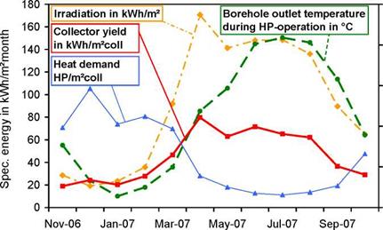
The measured monthly mean values in Fig. 2 show a strong seasonal variation. Therefore it is necessary to analyse the total energy fluxes and the performance factor at least on a one year lasting time scale.
![]()

 25
25
20
15
![]()
![]() 10
10
5
0
The HP delivers 33.3 MWh/a of heat energy, which covers the demand of the floor heating system (70%) and the domestic hot water system (30%). The annual HPS performance factor (HPF) amounts to 4.0, if the power demands of collector and borehole pump are neglected. With these additional consumers the HPF is 3.5.
The measurements show a 20% higher electric power consumption of the HP compared to the manufacturer information. With the promised efficiency of the HP, the HPS would come up to an annual performance factor of 5.0. The measured collector yield of 545 kWh/m2a covers the annual heat demand on the evaporator side of the HP.
Further results can be derived from the measurements:
• The unglazed collector charges the borehole during summer. The borehole reaches a maximum monthly mean outlet temperature of 20°C during HP operation.
• A high specific collector yield of 545 kWh/m2a is reached. Due to collector operation during night with convective and condensing gains the collector yield in December is higher than the irradiation.
• The averaged measured outlet temperature of the BHS is 6°C. Typical design temperature of a HPS without solar thermal system amounts to approx. 0°C.
•
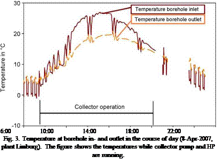 |
On summer days with high irradiation a temperature of 20°C to 25°C is reached at the source side of the HP (Fig. 3). In the following night the source side temperature can drop down to 10°C. This high temperature difference in the course of a day emphasizes the need of dynamic simulations to describe the accurate behaviour of HPS.
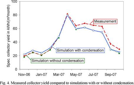 |
The collector model regarding EN 12975-2 is much more complex for unglazed than for glazed SC. In addition to the irradiance and the ambient temperature the wind velocity and the infrared radiation exchange is needed too. For collector fluid temperatures nearby or even below ambient temperature condensation on surface of unglazed collectors has to be regarded. The literature mentions condensation heat gains amounting to 5% up to 30% of the collector yield. A condensation model was developed [2] and validated by measured data and finally implemented in a TRNSYS collector type for unglazed SC.
Simulations of the Limburg plant show a total share of the condensation gains in the annual collector yield of 4%, maximum daily shares of up to 30% have been observed. During the winter period condensation heat gains reaches highest fractions of the collector yield (average value 14%). Considering condensation the difference in simulated and measured collector yield drops from 8.4% down to 5.3% (Fig. 4). It is assumed, that the residual difference is primarily caused by fundamental problems in measuring the representative wind velocity and ambient temperature over the large area of the unglazed collector array.
2. Simulation Results and Conclusion
The single components and the whole HPS were modelled in TRNSYS and validated using the measured data. A long period of validation is very important, because the operational behaviour of the HPS shows a significant difference between summer and winter.
Subsequent to validation a reference system is built up in TRNSYS and the correlation between annual HPS performance factor (HPF) and the main influencing factors such as collector area, borehole length etc. is investigated. The boundary conditions of the reference system are shown in Tab. 1.
Tab. 1. Boundary conditions of the reference system simulated in TRNSYS
|
Parameter |
Value |
|
Space heat demand |
60 kWh/m2a |
|
Radiator heating |
40°C |
|
Domestic hot water, 4 persons |
170 l/d at 45°C |
|
Heat pump |
7.5 kW thermal |
|
Total heat demand |
11 MWh/a |
|
Collector tilt angle |
45°, azimuth 0° (south) |
|
Weather region |
TRY 7 (Kassel) |
|
Heat conductance of the soil |
2 W/mK |
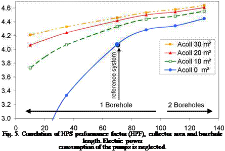
Fig. 5. shows as simulation results the course of HPF as a function of the borehole length an the collector area. If the power consumption of the collector pump is considered, the HPF is reduced by AHPF = 0.2 (energy class A) and AHPF = 0.4 (energy class D)[1] respectively.
There is not only one target variable for system dimensioning according to Fig. 5. The choice of collector area and borehole length leads to two possible targets: energy saving and investment cost. The standard borehole dimensioning of the reference system based on VDI 4640 leads to a borehole length of 70 m and a simulated HPF of approx. 4.0. Starting from this design point the HPF increases from 4.0 up to 4.4 by adding 20 m2 collector area to the HPS. The same improvement may be achieved by using a borehole depth of 130 m instead of 70 m. The same HPF in the reference system may be achieved, if a short borehole of 35 m will be regenerated by a 10 m2 collector array.
Beside saving of investment cost (BH length) and current cost (electric energy consumption) the usage of collector in HPS enhances the planning certainty of the whole system. The curves of the systems with collector are much more flat than the curves without collector (Fig. 5). Thus extreme supercooling of the BHE caused by improper dimensioning of the system can be prevented by integrating a collector. E. g., a difference in thermal conductivity of the soil of 1 W/mK instead of
2 W/mK decreases the HPF of the reference system from 4.0 down to 3.7. The system with 20 m2 collector area is almost unaffected by this modified thermal conductivity. Similar positive effects of the collector may be stated, if the real heat demand of the building is higher than assumed for the design process.
Borehole length in m
Beside collector area and borehole length additional parameters influence the HPF. Based on a solar assisted HPS (15 m2 collector area, 70 m borehole length) the influence of other parameters on the HPF is investigated (Tab. 2). Changing the heat conductance of the soil or the weather region effects the system by up to AHPF = 0.2. On the side of the heat consumption (supply temperature of the space heating and domestic hot water system) the influence on the HPS is much stronger.
Tab. 2. HPF sensitivity of reference system with collector to changes in system parameters (design point:
collector area 15 m2, borehole length 70 m, HPF = 4.4)
|
Influencing parameter |
Value in ref. system |
Changes |
AHPF |
|
HP-characteristic |
COP 0/35 = 4.6 |
WP 1 COP 0/35 = 4.4 WP 2 COP 0/35 = 4.7 |
-0.3 +0.1 |
|
Heat conductance of the soil |
2 W/mK |
3.6 W/mK 0.4 W/mK |
+0.1 -0.3 |
|
Space heating system |
Radiator 40°C |
Radiator 50°C Floor heating 35°C |
-0.4 +0.2 |
|
Domestic hot water system |
Tstorage = (45+3)°C |
Tstorage = (60+3)°C without DHW |
-0.6 +0.4 |
|
Space heat demand |
60 kWh/m2a |
30 kWh/m2a 100 kWh/m2a |
+0.1 -0.3 |
|
Weather region |
TRY 07 |
TRY 15, TRY 06 |
-0.2 |
It may be summarized, that a HPS without SC is much more sensitive towards modifications on the source side. The solar collector in a HPS minimizes the risk which may be caused by unforeseen high heat extraction or a lower ground heat conductance.
The project „Unglazed Solar Collectors in Heat Pump Systems: System Concept and Dimensioning” is funded by ’’Deutsche Bundesstiftung Umwelt (DBU)” (AZ 21098). The authors gratefully acknowledge this support and carry the full responsibility for the content of this paper.
[1] R. Tepe, M. Ronnelid, B. Perers, (2003). Swedish Solar Systems in Combinations with heat pumps, ISES Solar World Congress, Goteborg.
[2] Eisenmann W., Muller O., Pujiula F., Zienterra G. (2006): Metal Roofs as Unglazed Solar Collectors, Coupled with Heat Pump and Ground Storage: Gains from Condensation, Basics for System Concepts. EuroSun 2006 (6th ISES-Europe Solar Congress, 27.-30.6.2006, Glasgow).