Как выбрать гостиницу для кошек
14 декабря, 2021
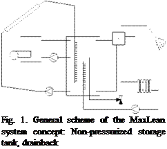 The heating system investigated in this work was designed as a simple yet competitive solar combisystem. The scope was to generate a system concept that can be easily integrated into the heating system of an existing house with water-based central heating and which, involving some further steps, is suitable for thorough cost reduction while maintaining a good thermal energetic performance. As such, drainback technology in combination with a pressure-less storage tank is foreseen, whereby the latter would possibly be made of plastics instead of steel, leading to a reduction of both material and production costs. The solar collectors are driven with water taken directly from the tank that also serves as a drainback vessel (see Fig. 1). The various peripheral components are connected to the storage tank by independent hydraulic circuits without any heat exchangers built into the store. The auxiliary heater loop is connected directly to the tank. All components included in this theoretical approach are readily available on the market, however none of the existing system concepts includes all of the features mentioned. A further conceptual modification has been developed regarding the
flat-plate collector circuit with stratifier, DHW plate
space heating system. Here a thermostatic heat exchanger, flow rate controlled heating loop
mixing valve is applied with a fixed set with stratifier.
temperature (50°C) such that a variation of the
volume flow rate (through the radiators or the heating floor) modulates the space heating power instead of the more commonly used flow temperature modulation with a mixing valve and a variable temperature set according to a heating curve. A comprehensive description of the system concept and the advantages of the improvements can be found in [1].
S. Bachmann, H. Drtick, H. Mtiller-Steinhagen
University of Stuttgart, Institute for Thermodynamics and Thermal Engineering (ITW) Pfaffenwaldring 6, 70550 Stuttgart, Germany Tel.: +49 711 / 685-63553, Fax: +49 711 / 685-63503
Corresponding Author, email: bachmann@itw. uni-stuttgart. de
Two solar combisystem concepts have been investigated where a compression heat pump is used as the only auxiliary heater. The investigations have shown that the combination of a solar combisystem with a heat pump can result in a promising approach for saving primary energy. This especially holds true compared with a monovalent heat pump system (without a solar thermal system). However, the investigated systems show a great difference concerning the electric energy consumption of the heat pump. Especially systems where the brine is solar preheated can offer a great reduction of electric energy consumption for the heat pump.
Keywords: compression heat pump, solar combisystem, seasonal performance factor, component testing
Heat pumps are presently enjoying a wide popularity in Europe. In 2007, the market for heat pumps showed a growth rate of about 100% in Germany. In recent years heat pumps were predominantly used as monovalent systems or in combination with a fossil fuel fired auxiliary heating system. At present, however, a number of new heating systems are being launched on the market where the heat pump is used as the only auxiliary heater for a solar combisystem. In addition to biomass heating systems, heat pumps offer the possibility of supporting the solar thermal system by, at least partly, renewable energy. Depending on the individual system design, there is a particular charm in combining heat pumps with solar thermal systems because this combination can provide an additional heat sink with a low temperature level so that the solar collector energy yield can be increased. For the heat pump on the other hand this approach offers a heat source with a relatively high temperature level which is beneficial for the coefficient of performance of the heat pump.
At the Research and Testing Centre for Thermal Solar Systems (TZS) in the Institute for Thermodynamics and Thermal Engineering (ITW), University of Stuttgart, two solar combisystems combined with a compression heat pump were investigated based on the component testing approach as described in the European Standard ENV 12977-2. One system consists of a compression heat pump where the condenser is located in the auxiliary section of the combistore. The other system uses an external compression heat pump in combination with an additional water store as heat source for the heat pump, which is exclusively charged by the solar collectors.
This paper presents the different system concepts. The results of the investigations such as the electric energy consumption of the heat pumps required to cover the total heat demand of the building, will be presented and discussed.
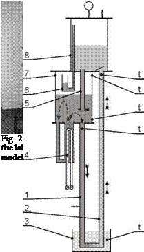
The schematic diagram of the laboratory installation and its photo are shown in Figs. 2 and 3. The warm and cold work vessels are made of cylinders and mounted one above another. The diameter and the height of the cylinders are 110 mm and 140 mm, respectively. Both cylinders are transparent and made of Plexiglas for visual observation. An electrical resistance heater with a capacity of 300 W was used as a source of heat. The heater had a temperature control for maintaining a few set-point temperatures. The control valve was made as a liquid seal. The heat exchanger (cooler) used for cooling the heat-carrier was located one metre below. The heat exchanger was made of a copper coil with a surface area of 0.15 m2 and placed into the cylinder vessel with a capacity of 7 litres filled with water. The vessel of the cooler was filled with water that was not running, but only accumulating heat leading to a temperature rise during the experiment.
The recorded data consisted of measurement of pressure inside the cold vessel and temperature measurements: at the top and the bottom of the inside warm vessel, at the descending pipe, at the
 |
up-flow pipe and at the vessel of cooler. Processes in the model are variable. It was decided to take measurements every 10 s since the duration of cycles was foreseen about 1 min and more.
 diagram of the passive heat transfer downward model:
4 — electrical heater, 7 — warm work vessel
5 — intermediate canal, 8 — cold work vessel,
6 — control valve (liquid seal), t — points of temperature
measurement
Experiments were done at a temperature of heat source of 33, 41, 49, 57 and 60°C.
The amount of heat carried by liquid heat-carrier from warm vessel during one cycle was calculated by using average temperature difference, tdescpipe measured at lower pipe and average minimum value of temperature, tup_flow pipe measured at up-flow pipe:
A. ТЬйг and S. Furbo2
1 AEE INTEC, Feldgasse 19, 8200 Gleisdorf, Austria
2 Department of Civil Engineering, Technical University of Denmark, 2800 Kgs. Lyngby, Denmark
* Corresponding Author, a. thuer@aee. at
Based on elaborated knowledge in international research projects within IEA-SHC Task 26 and the ALTENER project “Solar Combisystems”, a new solar combisystem concept was developed. Therefore the focus was concentrated on minimizing the temperature in the system with the goal to reduce system heat losses and to increase the efficiency of the condensing natural gas boiler and the solar collector. After development and test of the first prototype in the laboratory, a demonstration system was built which replaced an old conventional natural gas heating system in a one-family house. Measurements in practice showed how this new natural gas — solar heating concept performs in comparison with the old one. A Solar gain of 370 kWh and energy savings of 536 kWh per m2 collector area were achieved for the new solar combisystem. Domestic hot water consumption reduced by 20 % and hot water circulation losses of only 7% of hot water consumption was achieved. The average space heating temperature difference could be increased by 50% leading to lowest possible return temperatures. In spite of more installed pumps and valves the electricity consumption of the heating system could be decreased slightly.
Keywords: solar combisystem, energy savings, measurements
The project REBUS — „Competitive solar heating systems for residential buildings” was carried out from 2003 to 2006 with the goal to develop new concepts for solar combisystems in cooperation with industry partners [1]. Prototypes were first built and tested in the laboratory and further on installed in one family demonstration houses for in-situ long time testing and measurements. According to national boundary conditions PhD projects in Sweden and Latvia worked on solar combisystems in combination with pellet boiler and in Norway and Denmark solar combisystems in combination with natural gas boiler were investigated.
This paper summarizes the final results of the Danish PhD project where a new compact solar combisystem concept with direct integration of a condensing natural gas boiler was developed, tested as a laboratory prototype and finally installed as a second generation prototype in a demonstration one family house [2, 3, 4, 5].
The demonstration one family house with 3 occupants is situated in a small city about 40 km north of Copenhagen/Denmark. The old heating system was a non-condensing natural gas boiler (construction year 1990) with 22 kW nominal power in combination with a 50 Liter domestic hot water tank. The heating system consists of old cast iron radiators with thermostatic valves. This old
1
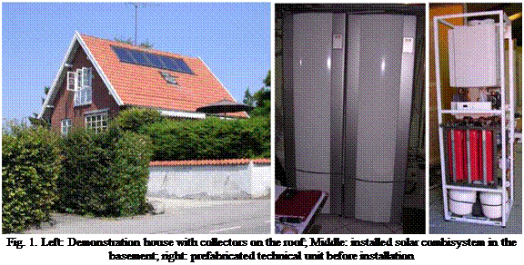 |
heating system was monitored in the period August 2004 to April 2006. In spring 2006 the new solar combisystem was installed: collector area of 6.75 m2 and 360 litre solar tank in combination with a condensing natural gas boiler (Milton Smart Line HR24). Beside the installation of the new solar heating system also two additional rooms were prepared to be used in the basement: one living room and a bath room, both equipped with floor heating. Monitoring of this new system started in October 2006.
Two previous studies have been undertaken investigating ISAHP systems. The first study involved developing a model in TRNSYS [12], a transient simulation program, to investigate the feasibility of the system, performing both a performance and cost analysis. The second study involved building a prototype of the system, and performing a range of constant temperature input tests, comparing the results with the simulated results. A brief description of each previous study is provided below.
The first study was conducted in the Solar Calorimetry Lab by Freeman [3] and simulated the performance of indirect solar assisted heat pump using TRNSYS. The program used mostly component models developed with the TRNSYS software, but models were created for the heat pump, the natural convection heat exchanger, and the heat pump controller. A detailed description of the TRNSYS model, and a theoretical analysis and derivation of the steady-state vapour compression heat pump model is given by Freeman [3], and is briefly summarized in a previous paper by the authors [13].
Results of these previous studies predicted higher seasonal solar fractions than conventional Solar Domestic Hot Water (SDHW) systems. It was concluded that the ISAHP gathered more energy from the environment during marginal weather conditions, as well as during the winter when compared to either an SDHW or air-to-water heat pump systems. The study also found that the life cycle cost of the ISAHP system showed up to 29% savings over the SDHW system for major cities across Canada.
The conventional dimensioning of a solar heating system for one — or multi-family houses is commonly based on a trade-off between the solar fraction and the level of utilisation [2], whereas the customer and user might rather be interested in elements like additional cost and primary energy savings. To meet these requirements a different dimensioning directive was introduced [1][3]. The simulation program TRNSYS was coupled with the optimisation program GenOpt for the dimensioning in response to this directive. A short description and the resulting optimal dimensions of the MaxLean system concept are given in the following and serve as basis for the subsequent sensitivity analysis.
The objective function minimised by the optimisation algorithm is the cost/benefit ratio described in Eq. (1):
|
a*I0 + BMaxLean Bref |
a annuity factor
I0 total investment costs of the solar thermal system
BMaxLean annual operation costs of the MaxLean system concept (including the heating circuit)
Bref annual operation costs of the conventional reference system
Eprim, sav primary energy savings
As long as a solar heating system is not economically rewarding, the primary energy saving is the preferential merit on which value is laid. The additional cost for these primary energy savings consists of the additional investment cost minus the difference in operation costs between the conventional and the solar assisted heating system. The investment costs of a solar heating system are calculated by Eq. (2), (cf. [2]):
A ( V � 6536
I0 = 2559€ + *368€ + 3983€I I Eq 2
m2 t m3 I 4′
Acoll flat-plate collector area
Vstor storage device capacity
The annual primary energy savings are calculated from the difference between the energy consumption of the solar and non-solar heating system, as well as the embodied energy of the solar system. (Thus, the embodied energy of the non-solar heating system —i. e. a water heater store— is not accounted for). The gas and electricity consumption is converted to primary energy consumptions. To obtain annual values of the embodied energy the total amount is divided by the service lifetime.
Solar thermal plants in the district heating scale were pioneered in Sweden the beginning of the 80’s. Since then a significant number of plants have been built around Europe, both with diurnal and seasonal storage. The technology was developed to a mature stage during the 90’s when a multitude of plants were built around Europe. Most of the plants today are found in Austria, Denmark and Sweden. Also in Germany there are a number of plants in operation. The difference in land prices between the northern and central Europe is probably the reason, that in Sweden and Denmark the collector arrays have been mostly built as ground mounted, whereas in central Europe they are normally mounted on roofs. The large number of solar assisted block heating plants in Austria is mainly thanks to generous subsidies, which have been around 40% of investment costs. Another fact that has made it feasible there is that traditionally the block heating networks were shut down for the summer to avoid the high heat losses. A new summertime heat supply business could be started when investing in solar and could be seen as extra income. The situation is different from the northern European view, where summertime district heating (even though with bad thermal efficiency) is taken for granted, and solar thermal is seen only as a means to save fuels. [1-12]
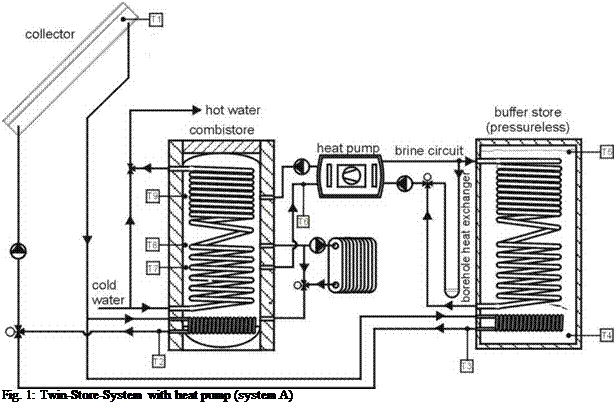 |
In the Twin-Storage-System (see figure 1) a combistore (nominal volume 600 l) is used for hot water preparation (by means of a stainless steel tube) and for space heating. It is charged by the collector via an immersed heat exchanger located in the lower part. The auxiliary part of the combistore is charged by the heat pump. Another pressureless buffer store (nominal volume 800 l) serves in addition to the borehole heat exchanger as a heat source for the heat pump. This store is charged by the solar collector only.
2.1. System with integrated heat pump (system B)
In this system (see figure 2) the heat pump exclusively uses a borehole heat exchanger as heat source. The heat pump is fitted at the combistore (nominal volume 750 l) and the condenser is located in the auxiliary part of the combistore. The return flow of the space heating loop is connected to the combistore using a special device for stratified discharging of the store. The heat gained by the collector is added to the combistore via an internal heat exchanger which is also equipped with a special stratification device. An external heat exchanger is used for hot water preparation.
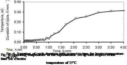
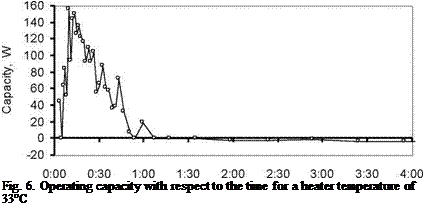
Temperature control of the heater has been set at 33°C in the first experiment. Temperature in the up-flow pipe was greater than in the tank-accumulator during the first hour. When these temperatures became equal, the rising of temperature in tank-accumulator stopped at the level of 25°C (see Fig. 4). The duration of the cycles became longer (see Fig. 5), and heat accumulation was discontinued (see Fig. 6). Greater duration of cycles occurs when water in the accumulator is heated up completely and the heater fills only thermal losses. The difference in temperature between the descending pipe and the up-flow pipe was about 7°C. Only 0.6 liters of water flowed through heat exchanger during one cycle independently of heat source temperature.
 |
The behavior of process was similar for other temperatures of the heater (see Fig. 7).
Time, h:mm
|
Time, h:mm Fig. 7. Operating temperature in tank-accumulator for heater temperature of 33, 41, 49, 57 and 60°C |
2.
 |
Testing of laboratory model demonstrated stable operation and the heat flow depended on the capacity of the heater. This model of the circulating pump starts to act autonomously when the temperature difference between the descending pipe and the up-flow pipe exceeds 7 degrees. The proposed device can be used when heat has to transfer from a heat user source which is located below it, and can especially be used with a solar installation instead of an electrical circulating pump. The testing of a device which is integrated with a solar installation is currently underway.
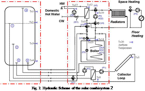 |
The complete solar combisystem consists of two units, the “Technical Unit” and the “Solar Store Unit” (see Fig 1 and Fig. 2).
In the technical unit all components like boiler, pumps, mixing valve, switching valves, heat exchangers, hot water preparation unit, expansion vessels, etc. are pre-installed. The main difference of this concept compared to existing ones, is the kind of integration of the condensing natural gas boiler. Due to the fact that the boiler is powerful enough for direct domestic hot water preparation, it can be avoided to heat the standby volume of the solar tank up to high temperatures for hot water preparation (typically 70°C or more). Therefore, the standby volume is only used at the temperature level needed for space heating operation, which results in much lower average temperature of the complete system and leading to higher overall performance of the heating system thanks to reduced heat losses of the tank and the pipes as well (detailed simulation results are presented in [2]). If hot water demand occurs and the temperature in the top of the solar tank is not high enough, the gas boiler immediately starts running in hot water preparation mode at high temperature level for direct hot water preparation in combination with the flat plate heat exchanger (see Fig. 3).
|
Further advantage for the condensing natural gas boiler is the very low return temperature during domestic hot water preparation leading to higher condensation rate and higher efficiency. During periods where space heating load is less than the minimum power of the boiler which can be reached by modulation (5.7 kW) the use of the standby volume reduces significantly the start/stop frequency leading to less start/stop emissions and longer life time of the ignition unit in the boiler.
Due to this operation concept also the top of the solar tank (Tc1) never is heated to high temperatures by the boiler resulting in a higher heat storage capacity of the tank for the solar heating system.