Как выбрать гостиницу для кошек
14 декабря, 2021
R. E. Critoph
University of Warwick, Coventry, CV4 7AL, UK.
R. E. Critoph@warwick. ac. uk
Abstract
An ‘alpha-version’ solar adsorption refrigerator for chilled food preservation is being developed jointly by the University of Warwick and Advanced Technology Materials Inc. The requirement is to cool a 5m3 insulated container in temperatures up to 40°. The prototype uses an ammonia — active carbon pair in a 2-bed cycle with heat and mass recovery. An ice-bank is created within the container during the day to act as a thermal store. The driving heat is supplied by 10m2 of evacuated tube collectors via a pressurised water loop. Simulations suggest that between 1 and 2 kW of cooling can be supplied given reasonable levels of insolation and that the adsorption cycle time may be made a simple function of insolation alone.
Keywords: Solar Adsorption Refrigeration Ammonia
Previous research at the University of Warwick on a mobile air conditioning system [1] has resulted in a patented concept [2] for a highly compact solid sorption reactor. In the work reported here the technology is applied to solar powered refrigeration. There is a requirement for maintaining chilled food at 0-5 °C in transportable containers in remote areas away from grid electricity. The conventional technology solution is to use vapour compression refrigeration powered from motor-generator sets. The University and Advanced Technology Materials Inc. (USA) are collaborating in the development of a solar thermal powered system, which will have parasitic power for controls etc. delivered by PV’s. The ‘alpha’ version, is due for field testing in Arizona from November 2008.
The standard insulated container, manufactured by CMCI (Figure 1) has external dimensions 2.4 m x 1.5 m x 2.1 m and internal volume of 4.7m3 . It is normally cooled by a conventional vapour compression chiller, rated at about 2kW cooling at 2°C. It is required to maintain normal use at ambient temperatures of 40°C using a solar thermal cooling system.
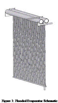
Naturally, any solar powered system requires thermal storage and it has been decided to use an ice bank integrated with the flooded evaporator of the refrigerator. Approximately 50 kg of ice is needed and this is incorporated into a vertical wall within the container. The wall has enough fins extending into the cold space so that cooling within the container is achieved by natural convection. Figure 2 shows the complete evaporator/ice-bank assembly and Figure 3 shows the flooded evaporator alone.
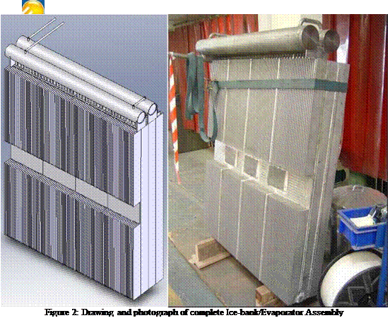 |
The evaporator consists of approx. 40 vertical half inch diameter tubes with a large reservoir above and parallel feed below. Later versions will have direct expansion evaporators which will have the advantages of lower mass, lower cost and reduced refrigerant charge, but the overwhelming advantage of a flooded evaporator is that requires less development and is comparatively risk free. Each of the vertical tubes fits tightly between the fins of an aluminium extrusion that forms part of the ice-bank. Without this heat transfer enhancement, towards the end of the process of freezing the water, the evaporating temperature would drop significantly as heat from the freezing front had
 to be conducted through an increasing thickness of ice, thereby reducing the system COP (cooling power / driving heat input).
The same aluminium extrusion is used on the outside of the ice tank to transfer heat to the cold space.
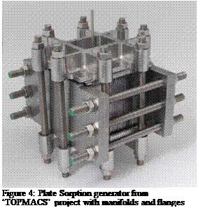
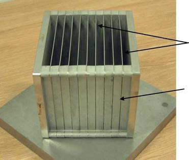
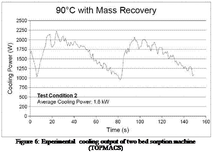
The refrigeration system is based on an adsorption cycle using ammonia as refrigerant and active carbon adsorbent. The plate heat exchanger (sorption generator) developed for this and other applications is shown in Figures 4 and 5. It is of low thermal mass (for good COP) and allows rapid cycling which reduces the physical size of the sorption generator for a given cooling power. Two of these generators, about 200mm on one side have been used in ‘TOPMACS’, an EU project to create a car air conditioning system that is driven by the waste heat of the engine. Laboratory operating results are given in Figure 6, which shows a mean cooling power of 1.6kW. The solar ice-making application is similar and design work is based on two similar but improved units. In the original generator, granular carbon in 4mm thick layers was sandwiched between stainless steel shims containing numerous water channels for heating and cooling the
carbon. The new design will utilise a more highly conductive (~2.0 W m K-1) carbon developed by ATMI
 |
which will enable the use of 12mm carbon layers, reducing cost, complexity and thermal mass. The two beds will be operated in a simple cycle with both mass and heat recovery, with typical cycle times of 2 minutes.

|
|
|
|
|
 |
The original design for car air conditioning was heated or cooled by unpressurised water. The solar collectors are expected to operate at well above 100°C and so the choice had to be made between using a heat transfer fluid or pressurised water. The heat transfer properties of water are so superior that pressurised water was selected.
A schematic of the whole refrigeration system is shown in Figure 7. Hot water from the solar collectors is pumped to either G1 or G2, heating the carbon within and desorbing ammonia. The ammonia flows through a check valve to the condenser where heat is rejected, through the float type expansion valve to the flooded evaporator / ice bank, where it boils and produces useful cooling. From there it passes through a check valve and into the other generator, where it is adsorbed. It is necessary to remove the heat of desorption via another pressurised water loop to an
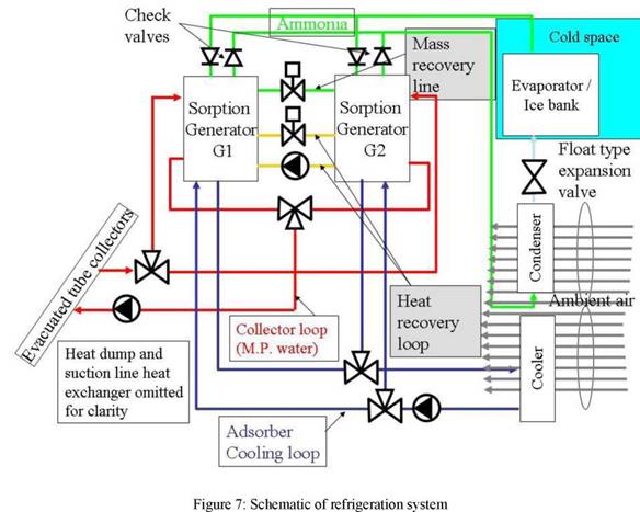 |
air cooled heat exchanger. At a suitable time (optimised for maximum cooling power) the cycle is reversed and the bed that was desorbing becomes the adsorber and vice versa. At the change-over, the performance can be improved, firstly by briefly opening the mass recovery line to equalise pressures in the two generators and then by using the heat recovery loop to pre-heat one bed with the reject heat of the other.
Given the high collector temperatures, the only commercially available options are evacuated tubes. The collectors used in our simulation models are Thermomax DF100 2m2 panels which feature direct flow of the fluid (water at up to 8 bar pressure) through the tubes. Figure 8 shows the manufacturer’s performance data. 10m2 collector area will be used to obtain a peak cooling power of up to 2 kW at an ambient temperature of 40°C in a desert environment.
A critical area of design is the waste heat rejection from the condenser and adsorbers. This is done using conventional fan coils and with attention being paid to minimising the fan power. The design compromises are critical. A small compact heat exchanger may have higher temperature differences which lead to lower COP and hence more heat to be rejected. It may also need more fan power and since parasitic electrical power will be met from PV, this must be minimised. Conversely, very large heat exchangers could be both impractical and costly. The compromise chosen uses a direct condenser measuring 650 h x 900 l x 570 w and with a 66W fan motor and a cooler measuring 650 h x 900 l x 470 w with a 102W fan motor.
|
Collector efficiency, G=1000W/m2, Tamb=40°C
Figure 8: Performance curves of chosen evacuated tube collectors |
The operation of the complete system has been modelled in Matlab to assist the design. The operation of the chiller has to be modelled at a timestep of about 0.001 s which is obviously impractical for modelling several days of operation. This problem has been overcome by deriving a pseudo-dynamic model in which the chiller is assumed to respond much more quickly (within minutes) than changes in the load or ambient conditions.
|
Figure 9 : Performance envelope for ambient temperature 30°C and evaporating temperature -10°C |
An example of the approach is given in Figure 9 in which each point (derived from detailed simulation every 0.001 s) corresponds to a balance between the heat input from the collectors at the particular insolation and ambient temperature, together with a particular cycle time (control
parameter) and evaporating temperature (corresponding to the state of the load). The envelope of the points (linear and quadratic are shown) gives the instantaneous cooling power corresponding to the best control strategy for that particular evaporating temperature and ambient temperature for the full range of insolation.
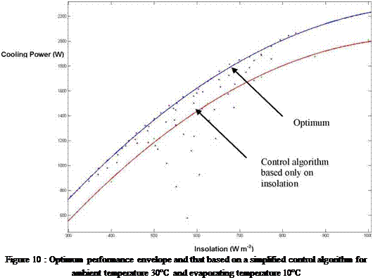
A set of these correlations for a range of evaporating and ambient temperatures may be combined empirically to yield a polynomial function for optimum cooling power under any conditions which can act as input to the model of the ice-bank and cold box. Preliminary examination of these results implies that the cycle time can be made a simple function of insolation only (i. e. ignoring ambient and evaporating temperature) with comparatively little penalty. Figure 10 illustrates this for the particular case of an ambient of 30°C and evaporating at 10°C.
As comes out of preceding relations, guidelines for dimensioning of air-soil heat exchangers relate to careful examination of convective and diffusive heat exchange coefficients, which themselves depend on geometrical parameters (eq. 5-6).
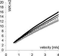
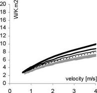
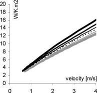
As is given by eq. 5, the convective air/pipe heat exchange ha increases almost linearly with air velocity, with a lesser dependence on pipe diameter, reaching values between 4 and 16 W/K. m2 for velocities between 1 and 4 m/s (fig. 3, left column).
Diffusive heat exchange on its turn depends on the available soil layer around the pipes and the way heat diffusion can actually take place. We therefore will consider two distinct geometries, with quite different
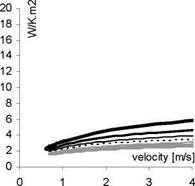
the airflow may be charged and discharged in the soil in the same radial way as before (fig. 2, right). To the contrary, charge and discharge of the yearly heat wave saturates the immediate vicinity of the pipes and can hence only take place in plane mode, downwards into the ground, on a surface S defined by the system size (length by width). Accounting for the reduced available capacity, the diffusive coefficient h now reduces to 0.6 W/K. m2, which forces the resulting amplitude-dampening coefficient to some 0.5 W/K. m2, independently of air velocity (fig. 3). As a consequence, such a geometry enables to reach daily amplitude-dampening with the same pipe length as before, but almost without dampening of the yearly amplitude (see also fig.5). Note that such a compact geometry may also be realized in a multi-layer configuration, in which case the slight effect on yearly amplitude will be all the more negligible.
For both the above defined geometries it is now possible, via equation 3, to give dimensioning rules in terms of necessary pipe length for “complete” amplitude-dampening, which we define as a residual amplitude of e-2 ~ 15%. The resulting guidelines are as follows:
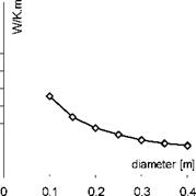
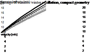
• If the point of interest concerns dampening of the yearly oscillation, it is necessary to work with distant of each other and deeply buried pipes, with approximately 3 m soil around each. In this case, a rough dimensioning rule for complete amplitude-dampening is 30 m pipe per 100 m3/h airflow (fig. 4, left), for diameters yielding an air velocity in the 1 to 4 m/s range. As pointed out above, the daily amplitude will have vanished on approximately half that distance, with the same rules as hereafter.
• If the point of interest concerns dampening of the daily oscillation, only with slight or negligible dampening of the yearly component, it is sufficient to work with close to each other and shallow buried pipes, with approximately 15 cm soil around each. Typical required length is roughly 15 m per 100 m3/h airflow (fig. 4, right), a relation which however isn’t as linear anymore and slightly depends on the pipe diameter and associated air velocity.
Note that preceding guidelines for pipe length concern residual amplitude of e-2, but may be extrapolated by way of the exponential form of eq. 3. For example, the guidelines for the compact configuration (fig. 4) indicate that a 200 m3/h airflow in a 22 cm diameter pipe (~ 1.5 m/s) needs 55 m for complete daily dampening; a 20 m pipe hence would yield a residual amplitude of e — 2-(20/55) = 48%.
It should finally be stressed that the model on which these guidelines have been established does not take into account perturbation of the storage mechanism by thermal drive from upper surface (ambient or building), nor the possible effects of transient airflow or latent heat exchanges. As a complement to the basic guidelines elaborated in this study, these effects can however be investigated by way of numerical simulation.
ha : convective exchange (air/pipe) hs : diffusive exchange (pipe/soil) h : total exchange (air/soil)
 |
 |
|
 |
 |
|
Storage of day/night oscillation, extensive or compact geometry
Storage of summer/winter oscillation, extensive geometry
 |
20 18 16 14 12 10 8 6 4 2 0
|
1 |
2 3 |
4 |
0 |
0.1 |
0.2 0.3 |
0.4 0 |
1 2 |
3 4 |
|
20 cm — |
25 cm |
|
diametre |
Fig. 4: Guidelines for dampening of daily or yearly amplitude.
Validation as well as illustration of these behaviors and guidelines will now be given on hand of an extensively validated finite element numerical model for buried pipe systems [4], which accounts for fully three dimensional heat diffusion in soil and flexible border conditions, as well as for sensible and latent heat exchanges (latter not used within this study).
Both the considered configurations consist of a layer of 20 cm diameter pipes, each swept by a 200 m3/h dry airflow, with hourly input given by the standard annual meteorological temperature for Geneva. The pipes are buried in a soil with same thermal characteristics as above, in one case at 310 cm depth (center of pipe) and with 620 cm inter-axial distance, in the other case at 25 cm depth and with 50 cm inter-axial distance. Superior border conditions are in both cases taken as adiabatic, whereas a sufficiently important soil layer is taken into account for the heat wave to expand as deep as necessary (adiabatic border conditions 15 m below pipes). The arrays are supposed to consist of a sufficient amount of pipes for lateral border effects to be negligible, so that the system may be described by way of a unique pipe (adiabatic conditions at inter-axial distance).
Simulated hourly temperatures are depicted in form of daily minima and maxima profiles at 0, 20 and 50 m distance (fig. 5, top), and confirm preceding analysis: deep and wide apart buried pipes induce combined daily and yearly amplitude-dampening, eventually reaching the constant annual average, whereas the compact pipe configuration essentially allows for daily amplitude — dampening, with a constant output over the day/night period but an almost unaltered seasonal trend.
The hourly data at every 10 m is Fourier analyzed, so that residual yearly and daily amplitudes may be compared to the values given by the above dimensioning rules (fig. 5, bottom): a very good correlation is manifest in either case, theoretical guidelines only slightly overestimating the residual amplitudes given by numerical simulation.
[1] Hollmuller P., Lachal B. (2001) Cooling and preheating with buried pipe systems : monitoring, simulation and economic aspects. Energy and Buildings, 33(5), p. 509-518.
[2] Hollmuller P. (2003) Analytical characterisation of amplitude-dampening and phase-shifting in air/soil heat-exchangers. International Journal of Heat and Mass Transfer, vol. 46, p. 4303-4317.
[3] Gnielinski V. (1975) Neue Gleichungen fur den Warme — und Stoffubergang in turbulent durchstromten Rohren und Kanalen, Forsch. Ing.-Wes., Vol.41(1), pp. 8-15.
[4] Hollmuller P., Lachal B. (2005) Buried pipe systems with sensible and latent heat exchanges : validation of numerical simulation against analytical solution and long-term monitoring, in : Building Simulation, proceedings of the 9th International Building Performance Simulation Association, 15-18 August 2005, Montreal, Quebec, Ecole Polytechnique de Montreal, Vol.1, p. 411-418.
1Tchanche Fankam Bertrand*, 1George Papadakis, 1Gregory Lambrinos and 2Antonios
Frangoudakis
Department of Natural Resources and Agricultural Engineering,
1 Laboratory of Agricultural Engineering,
2 Laboratory of Agricultural Constructions,
Agricultural University of Athens, 75 Iera Odos Street 11855 Athens, Greece Tel.: +30 (210) 529 4046; Fax: +30 (210) 529 4036 * Corresponding author, e-mail address: tfb@aua. gr
Abstract
This paper deals with the study of the effects of regeneration on low-temperature solar organic Rankine cycles utilizing R134a as working fluid. The configurations investigated are: basic ORC (organic Rankine cycle), regenerative ORC with internal heat exchanger, regenerative ORC with open feedwater heater and regenerative ORC with closed feedwater heater. The effects of the regeneration is assessed using a method of thermodynamic exergetic analysis called exergy — topological method based on the combination of exergy flow graphs, exergy loss graphs and thermoeconomic graphs. For a designed output power of 2 kW, the incorporation of an open feedwater is the most efficient way to increase the system performance. The thermal and exergetic efficiencies obtained were 3.95% and 9.16% respectively; this represents an increase of 6.83% and 6.93% in thermal and exergetic efficiencies respectively compared to the simple Rankine engine. The configuration with closed feedwater heater produces similar results but is less efficient. The incorporation of an internal heat exchanger produces negative effects. Keywords: organic Rankine cycles, exergy-topological method, regeneration, solar energy
1. Introduction
The lack of electricity or means of power generation seriously limits the development of many regions around the world. The increasing fossil fuels prices and the pollution derived from their combustion in power plants are two important reasons for which the attention should be shifted towards renewable energy sources. As can be seen today, the price of oil will still increase and the access to grid electricity will become more and more difficult for populations leaving in remote areas. In this context, solar energy can play a major role in sunny areas. Recent works [1-3] on low-temperature organic Rankine cycles show that this technology could be a solution for providing fresh water and electricity, and perhaps thermal comfort. Although the system’s components are well known technologies, the integration to a fully and efficiently working system is a challenge. A serious drawback of the low-temperature organic Rankine cycle is its low efficiency. An examination of the basic Rankine cycle reveals that the heat is transferred to the working fluid at relatively low temperature; this reduces the system thermal efficiency. A solution to remedy this shortcoming is to use a regenerator or a recuperator, which gives birth to several organic Rankine cycle configurations.
In this paper, the effects of the regeneration on the modified cycle with internal heat exchanger and regenerative cycles with open and closed feedwater heaters are analyzed using a new exergy approach called exergy-topological method [4-7].
Subproject SP6b is similar to SP6a. It is designed to condition a lecture room (17 people, 95 m2) and an office room (10 people, 80 m2) in the new office building, Solar XXI, at INETI and to warm up a DHW tank (0.4 m3) for lab washing purposes.
The main differences from SP6a are:
• The fuel used for the CHP — biodiesel (consequent lower thermal and electrical CHP output)
• The use of a chilled water tank in the cooling circuit
• The load demand (specific heating and cooling as well as DHW — consequent different number of running period, number of on/off cycles)
• Some details in the hydraulic circuit like, for example, a heat exchanger physically separating the chilled water loop from the main CHCP system circuit.
1.1. Design of the solar cooling plant
The Fraunhofer institute UMSICHT in Oberhausen has operated a solar cooling plant since summer 2002. The solar cooling plant supplies cold water via a cold water network for space cooling. The cooling power of the solar cooling plant is provided by an absorption chiller with a target cooling power of 58 kWth. The absorption chiller is hot water driven, which is heated up by a solar collector field with a size of 108 m2. Figure 1 shows the process scheme of the solar cooling plant.
solar collector field
he cold capacity of the solar cooling plant is generated by a single-effect LiBr-absorption chiller type WFC-10 from the manufacturer Yazaki. The cold capacity of the absorption chiller is variable from 25 to 58 kWth that based on the cooling water temperature. The chiller COP is 0.65 to 0.75 at nominal operation condition and cooling water temperature of 24/31 °C, reported by the manufacturer. The refrigerant of the absorption chiller is water and the absorbing agent is a LiBr-solution. The solar collector field consists of nine field parts with a total collector size of 108 m2 Each part consists of eight vacuum tubes collectors type Lux 2000 from the manufacturer Soleado, Germany. The installation is on the roof of the institute building C orientated in southern direction. In its present stage of extension, the solar collector field provides 50 kWth heat power on the temperature level of 105/98 °C at a solar irradiation of 900 W/m2. In the final stage of extension, the solar collector field will be still enlarged and the heat power will rise to 78 kWth. The heat transfer fluid flows directly through the vacuum tubes (no heat pipe system). The stagnation temperature of the solar collectors is 223 °C. In order to prevent damage from the solar collector by overheating, surplus heat can be discarded by a stand-by cooler, which is installed in parallel to the solar collector field. An evaporative cooling tower is used as re-cooling device for the absorption chiller and serves also as cooling device for free cooling. The re-cooling power of the cooling tower is 134 kWth at a wet bulk temperature of 21 °C and cooling water temperature of 24/31 °C. The volumetric flow rate of the cooling water over the cooling tower has max. value of 15 m3/h. An additional heat exchanger, which is installed parallel to the absorption chiller enables to use the cooling tower for free cooling. The solar cooling plant is equipped with a 6.6 m3 solar energy storage in the hot water cycle and a 1.5 m3 cold water storage in the cold water cycle. The solar energy storage has a heat capacity of 230 kWhth at max. temperature of 115 °C and the cold water storage 7 kWhth at min. temperature of 6 °C. The total electrical connecting load of the solar cooling plant including all auxiliary drives and devices is 10 kWel, but the electrical power input is smaller than 3.5 kWel.
The absorption refrigeration system is considered a heat driven system that requires minimal to no mechanical power for the compression process. It replaces the energy-intensive compression in a vapor compression system with a heat — activated thermal compression system. A schematic of a single-stage absorption system using ammonia as the refrigerant and ammonia-water as the absorbent is shown in Figure 1. The condenser, throttle and evaporator operate in the exactly the same manner as for the vapor compression system. In place of the compressor, however, the absorption system uses a series of three heat exchangers (absorber, regenerating intermediate heat exchanger and a generator) and may require a small solution pump. Ammonia vapor exiting the evaporator (State 6) is absorbed in a liquid solution of water-ammonia in the absorber. The absorption of ammonia vapor into the water-ammonia solution is analogous to a condensation process. The process is exothermic and so cooling water, or a liquid-to-air exchanger, is required to carry away the heat of absorption. The principle governing this phase of the operation is that a vapor is
2
more readily absorbed into a liquid solution as the temperature of the liquid solution is reduced. The ammonia-rich liquid solution leaving the absorber (State 7) is pumped to a higher pressure, passed through a heat exchanger and delivered to the generator (State 1). The mechanical power needed to operate the pump, if used, is given by Equation 1, the same equation that applies to the minimum power needed by a compressor. However, the power requirement for the pump is much smaller than that for the compressor since v, the specific volume of the liquid solution, is much smaller than the specific volume of a refrigerant vapor. Absorptions systems that do not require the use of a mechanical pump, such as the system used in the present study, rely instead on gravity. In the generator, the liquid solution is heated, which promotes desorption of the refrigerant (ammonia) from the solution. Unfortunately, some water also is desorbed with the ammonia, and it must be separated from the ammonia using the rectifier. Without the use of a rectifier, water exits at State 2 with the ammonia and travels to the evaporator, where it increases the temperature at which refrigeration can be provided. This solution temperature needed to drive the desorption process with ammonia-water is in the range between 120°C to 130°C (248°F to 266°F). Temperatures in this range can be obtained using low cost non-tracking solar collectors. At these temperatures, evacuated tubular collectors may be more suitable than flat-plate collectors as their efficiency is less sensitive to operating temperature. p2
W comp, min = m I vdP Equation 1
p;
A number of barriers have prevented more widespread use of solar refrigeration systems. First, solar refrigeration systems necessarily are more complicated, costly, and bulky than conventional vapor compression systems because of the necessity to locally generate the power needed to operate the refrigeration cycle. Second, solar refrigeration systems operate at a much lower COP, 0.5 versus 3 for more conventional compressor based refrigeration systems.5 Although this not a critical flaw as the fuel for solar systems is free solar energy. Third, the ability of a solar refrigeration system to function is driven by the availability of solar radiation. Because this energy resource is variable, some form of redundancy or energy storage (electrical or thermal) is required for most applications, which further adds to the system size and cost. The advantage of solar refrigeration systems is that they displace some or all of the conventional fuel use. The operating costs of a solar refrigeration system should be lower than that of conventional systems, but at current and projected fuel costs, this operating cost savings would not likely compensate for their additional capital costs, even in a long term life-cycle analysis. The major advantage of solar refrigeration is that it can be designed to operate independent of a utility grid. Applications exist in which this capability is essential, such as storing medicines in remote areas.
|
Figure 1: Ammonia-water absorption refrigeration system.4 |
In May 2008 the worldwide first installation of a chillii® Cooling Kit 8 for a two family house in Alzenau, Germany based on a chillii® STC8 (Fig. 5.) was successfully put into operation. The necessary heat for driving the machine is provided by 24 m2 flat collectors and a biomass back-up. As a buffer 2.000 litre hot water storage is used. An electrically high efficient dry re-cooler with water spraying is used for an effective re-cooling of the 22 kW waste heat of the adsorption chiller. The cold distribution is effected by fan coils.
|
Fig. 5. Flat plate collectors on the roof of the two-family-house as well as the chillii® STC8 adsorption chiller and the dry re-cooler (sources: SolarNext). |
The chillii® Cooling Kit 8 is until now besides others installed in residential or office buildings in the following countries: Germany, Austria, Italy and China.
For the new training centre and office building of Bachler Austria, Austria a complete solar cooling system with biomass back-up has been installed between winter 2006 and spring 2007. The chiller that is used is a chillii® PSC10 (Fig.6.) for a required cooling load of 9 kW and as recooler a 26 kW wet cooling tower as well as in addition a swimming pool. The wet cooling tower is operated with very low re-cooling temperatures of 24/29°C for the Middle-European application. The requested solar heat is delivered by 40 m2 flat plate collectors, which are mounted at the faqade and on the ground and is stored in three hot water storages with 1.5 m3 each. The cold distribution is done by concrete core activation (cooled ceilings) with cold water temperatures of 16/19°C and a dew point thimble for cooling of the training and office rooms.
|
Fig. 6. Flat plate collectors on the facade and the ground as well as absorption chiller chillii® PSC10 at the training center and office building of the company BachlerAustria (sources: SolarNext). |
Further chillii® PSC10 absorption chillers are installed in different thermally driven systems worldwide, e. g. three in Germany, one in Canada and two in Malta. The current chillii® PSC12 is installed for the first time together with a chillii® Solar Cooling Kit 12 in Italy. A second chiller is now running in Spain.
With the chillii® WFC18 water/lithium bromide absorption chiller four chillii® Cooling Kits 18 for air-conditioning applications have been realized until now, one in Germany (bakery), one in Syria (residential building), one in Romania (university) and one in Australia (office building).
The energy demand for air-conditioning is rising rapidly in Europe and worldwide. Thermal cooling with solar thermal heat, district heat, process waste heat, CHP waste heat or biomass can reduce the energy consumption and the CO2 emissions considerably. But if a backup system is used, which is not based on renewable energy sources; the primary energy consumption rises again. Basically the solar fraction of solar cooling kits should be higher than 70% or an existent complete solar heating system would even be better. In the small-scale capacity range with up to 30 kW several water/lithium bromide absorption chillers; one ammonia/water absorbers as well as two water/silica gel adsorption chillers are recently available on the European market. For an economical operation of solar cooling systems the additional investment costs for the sorption chillers have to be further reduced, which is absolutely expected at higher sales numbers. At very low heat prices, for example at existing solar thermal plant for the heating support, thermal solar cooling systems can nearly compete today with common electrical compressor chillers. Because of the general trend in Europe to larger solar thermal plants for the heating support, small-scale sorption chillers offer good opportunities to use efficiently the summery heat.
[1] 71 Mio. Klimagerate — neuer Weltrekord, cci, 9 (2007) 30.
[2] U. Jakob, Overview on Small Capacity Systems, Proceedings of the International Seminar Solar AirConditioning (2008) Munich, Germany, 73-80.
[3] U. Jakob, Auch die Sonne kann kuhlen — Ein Uberblick uber Sorptionskaltemaschinen kleiner Leistung, Erneuerbare Energien, Vol. 18, 6 (2008) 64-70.
This part is aimed through a check list at answering the following question : is the project compatible with solar cooling technology? The different steps of the check list based on a scoring method are the following :
• general presentation of the list : what? how?
• questionnaire to fill in with scores for each question with values from 1 to 3
• analysis of the results of the scoring total values
• advice on the opportunity of a solar cooling project
|
Large industry utility |
Public office building |
Hotel |
|||
|
Building |
Climate |
3 |
3 |
3 |
|
|
Important area for solar collectors |
3 |
2 |
2 |
||
|
Space for the technical premises |
3 |
2 |
1 |
||
|
Distribution network adapted |
3 |
3 |
2 |
||
|
TECHNICAL |
Existing or planned conventionnal material adapted |
3 |
3 |
3 |
|
|
FEASIBILITY |
Load |
Daily adequation production <-> load |
3 |
3 |
1 |
|
Yearly adequation production <-> load |
3 |
2 |
2 |
||
|
Hot water and heating needs all year long |
3 |
2 |
2 |
||
|
Solar system unders izement possible with a back up |
3 |
3 |
2 |
||
|
Energy cost |
High level of substituted energy cost |
1 |
3 |
3 |
|
|
Reasonnable cost of water |
3 |
2 |
2 |
||
|
Bulling owner |
Possibility of making important investment |
3 |
3 |
1 |
|
|
ECONOMICAL |
Motivation of the bulding owner |
3 |
3 |
3 |
|
|
FEASIBILITY |
Importance of the mediatic impact |
3 |
2 |
3 |
|
|
Environmental politic actions |
3 |
3 |
3 |
||
|
Eligible to national and international grants |
1 |
3 |
2 |
||
|
Financial stability of the building owner |
3 |
3 |
1 |
||
|
ORGANISATIONAL FEASIBILITY |
O&M |
Skilled internal technical s taff |
3 |
2 |
2 |
|
Aware of O&M regular actions |
3 |
2 |
2 |
||
|
Monitoring |
Presence of a financed and long term telemonitoring |
2 |
3 |
2 |
|
|
TOTAL SCORE(on 60) : |
55 |
52 |
42 |
|
Fig. 2. Example of scoring for the check list method. |
K. T. Witte1*, J. Albers2, M. Krause3, M. Safarik4, F. Besana1, W. Sparber1
1 European Academy Bolzano, Institute of Renewable Energy, Viale Druso 1, 39100 Bolzano, Italia
2 Technische Universitat Berlin, Institut fur Energietechnik KT-2, Marchstrabe 18, 10587 Berlin, Germany
3 Fraunhofer Institute for Building Physics, Gottschalkstr. 28a, 34127 Kassel, Germany
4 Institute of Air Conditioning and Refrigeration (ILK), Bertolt-Brecht-Allee 20, 01309 Dresden, Germany
* Corresponding Author, kwitte@eurac. edu.
Abstract
In order to propagate the installation of solar cooling systems dimensioning and system design have to be optimised. Although the transient simulation software TRNSYS is well established for this purpose, considerable deviations to measured values are possible, when components are not correctly used or designed for the simulation. For this work two different models (so called Types) are investigated in parallel to simulate the part load behaviour of the absorption chiller EAW Wegracal SE 15. The paper reports on the possibilities and application limits for both TRNSYS Types. Their differences in accuracy regarding laboratory test data as well as real time data of a solar cooling system are discussed. The basic methodology as well as the applied modifications to adapt the TRNSYS — Types to the EAW chiller are described. Finally the necessity to improve both models for non-nominal flow rates is shown.
Keywords: Solar cooling, EAW absorption chiller, Simulation, Characteristic Equation
Solar Combi-Plus systems use solar energy to provide heat for domestic hot water and heating in winter as well as for domestic hot water and cold production in summer. Thus high solar fractions are possible over the year. Moreover such systems contribute to decrease the peak power demand during summer, which is partially caused by the growing number of small electrically driven airconditioning appliances in the sunny and hot southern countries of Europe [1]. For the optimum design of solar cooling systems computer simulations are essential. To validate these simulations real time data of Solar Combi-Plus systems are required. Therefore, the European Academy (EURAC) in Bolzano is monitoring one of them at the premises of Ebner Solartechnik, using the absorption chiller EAW Wegracal SE 15 [2]. For the simulation of this plant and its utilisation the simulation software TRNSYS [3] is used. In a first step the available component of the ‘standard package’ of TRNSYS Version 16.1 was chosen to simulate the absorption chiller (Type 107). Since the implemented control strategy of this Type as well as the performance data differ from real operation of the EAW Wegracal SE 15 chiller, both the source code and the performance data of Type 107 have been modified. In a second step, another model based on the method of characteristic equations [4] (Type 177) was adapted to the EAW chiller and the simulation results have been compared to the same measurements.
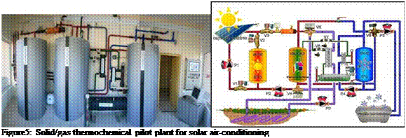 |
A solar air-conditioning pilot plant has been built and is currently running in PROMES laboratory (Perpignan France). This pilot, of a daily cooling capacity of 20 kWh, is based on a solid/gas thermochemical sorption process that is powered at 60-70°C by 20m2 of flat plate solar collectors. The thermochemical sorption process rests on the coupling of a reversible chemical reaction between a reactive solid (BaCl2) and a liquid/gas phase change of a refrigerant (NH3). Its functioning mode is intrinsically discontinuous and cyclic and is thus well adapted to the storage/transformation of solar energy. Indeed, the process comprises two main reactive phases that are carried out under different thermodynamic constraints: a diurnal regeneration phase followed by the useful production of cold during the night phase. During the first phase, the heat supplied to the reactor in the range of 50 to 70°C by the flat plate solar collectors enable the decomposition reaction of the reactive salt which releases the reactive gas that condenses in a condenser and accumulated at ambient temperature. When there is a surplus of solar energy, this one can be stored at 80°C by melting a phase change material (wax) for either enabling a faster heating of the reactor during the morning, or for domestic hot water production The cold production during the night consists in cooling the reactor which reabsorbs chemically the reactive gas that evaporates in the evaporator and thus producing the cold. The produced cold at -5°C to 0°C is stored in another PCM that solidifies below 4°C, in order to be delivered according to the cooling demand all along the day. An analysis of experimental results leads to an averaged efficiency of 50% for the solar collectors and a process COP ranging from 30 to 40%, leading thus to a daily cooling productivity for the thermochemical process of about 0.8 to 1.25 kWh of cold at 4°C per m2 of solar collector.
The investment cost of solar cooling systems is much higher than those of conventional air conditioning equipments. For instance, the cost of the sorption installations vary widely depending on the facilities, from 4000 €/kW up to 10 000€/kW, while the price for conventional compression air conditioning is around 300 €/kW. On the other hand, even if the technologies involved are common they are still poorly understood when set up in a building. Before considering a wide dissemination of these processes, it is necessary to fill a number of gaps concerning the estimation of energy, environmental and financial efficiency, the optimization of the thermodynamic processes and the lack of decision-making tools for pre studies and studies. To allow wider dissemination of solar cooling, the issues of research programs for the years to come are therefore
to reduce installation costs and to ensure optimum performance. The first expected result for ORASOL is to define what is the best cooling process according the building type and the climate. This answer will be brought by the analysis carried out by the pool 1. Then it is important to provide accurate but also validated simulation software for each solar cooling technology. These tools aim to support all research works on solar cooling and must also be used as a basis for more sophisticated ones as, for instance, sizing or optimization tools.