Как выбрать гостиницу для кошек
14 декабря, 2021
Several simulations were performed for the different buildings situated in Lisbon. For the office building, the best results occur for a collector area and a storage volume between 120-180 m2 and
0. 05-0.13 m3/m2, respectively; that represents a storage capacity between 1-5.5 hours. For the hotel, the best results occur for a collector area and a storage volume between 200-300 m2 and 0.01-0.07 m3/m2, respectively; that represents a storage capacity between 0.3-3.1 hours. For the single-family house, the best results occur for a collector area and a storage volume between 15-30 m2 and 0.05-0.13 m3/m2, respectively; that represents a storage capacity between 2.5-13 hours.
4.2 Energy, economics and emission savings
Considering a solar thermal system size that provides an annual solar fraction of 60%, for the office building and hotel, the solar fraction is higher for March and December; for the singlefamily house, the solar fraction is higher for April, May and October. The higher solar fraction is related to the lower energy need that occurs in those months.
4.4.1 Office building
Table 4 presents the energetic, economic and emission analysis for the system configuration with lower total cost of produced energy for a solar fraction of 60%.
For the office building there is no economic viability in any of the locations considered — see Figure 3.
In situations where an electric backup is not possible (only gas backup), the solar system installed in Rome with a solar fraction of 60% is economically more profitable.
A gas boiler as backup solution, instead of an electric compression chiller, allows a reduction in solar collector area between 3-9%, for the same solar fraction.
In the Mediterranean cities, the flat-plate collector compared to the vacuum tube collector, allows a reduction in the total cost of produced energy between 0-1.6 c€/kWh — see Figure 3. In Berlin, both collector technologies show similar results. Vacuum tube technology has the advantage of allowing a reduction of collector area between 30-50% — see Figure 4.
4.4.2 Hotel
For the hotel, in Rome it is possible to achieve economic viability for a solar system with gas backup and solar fractions between 20-40% — see Figure 3. Comparing with a conventional electric air-conditioning, this system leads to a reduction of 5 c€/kWh of produced energy. In situations where an electric backup is not possible (only gas backup), solar systems installed in Rome and Lisbon with solar fractions between 20-60% are economically interesting. A gas boiler as backup solution, instead of an electric compression chiller, allows a reduction in solar collector area between 0-20% for the same solar fraction.
In the Mediterranean cities, the flat-plate collector compared to the vacuum tube collector, allows a reduction in the total cost of produced energy between 0-2.8 c€/kWh — see Figure 3. In Berlin, both
5
collector technologies show similar results. Vacuum tube technology has the advantage of allowing a reduction of collector area between 20-50% — see Figure 4.
|
Table 4. Energy, economic and emission analysis for systems in Lisbon with gas backup and 60% solar fraction.
|
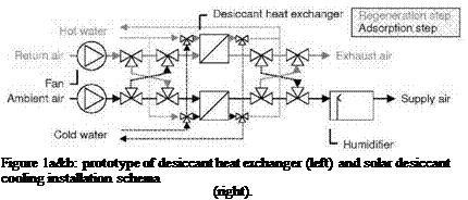 |
In order to propose an alternative to traditional desiccant cooling systems, using desiccant wheel, the CEA — INES, in collaboration with the CNAM-IFFI, developed a multifunctional exchanger (Figure 1a) able to couple heat and mass transfers of the desiccation.
The process air enters the heat exchanger by the centre and then flows in a radial direction between the desiccant bed and the periphery where the air is collected. To heat or cool the desiccant during regeneration or adsorption mode, a copper heat exchanger made of 30 tubes of 10 mm diameter with fins is immersed in the desiccant bed. The exchanger is filled with 50 kg of Engelhard KC — Trockenperlen-N type silica gel. The particles are of spherical shape with a mean diameter of 3.4
mm. The total mass of the prototype is 60 kg. The Figure 1b presents the scheme of a solar desiccant cooling installation using desiccant heat exchangers. The traditional two wheels (desiccant and heat recovery) are replaced by two desiccant exchangers (air and desiccant/water) functioning heated or cooled; the cooling corresponds to the drying step while heating is used for the regeneration. During the regeneration phase, hot water, flowing directly from solar collectors, is used. During the adsorption phase, cold water circulation, resulting for example from a cooling tower or geothermal sinks, maintains the adsorbent under optimal sorption conditions. The prototype of heat exchanger filled with adsorbent was tested and it appeared that the system is able to cool air from 33°C and 40% HR (outside air) to 24°C and 90% HR (blowing air) [1]. A TRNSYS numerical model of desiccant heat exchanger was also developed to simulate the heat and mass transfer for the adsorption and regeneration processes in the prototype. The results of the numerical model are in agreement with the experimental results [2], and systems performances could be evaluate.
We are going to present the simplified model of our installation whose principle scheme is shown on the Fig. 1. The aim is to simulate the behaviour of our installation in order to get a better understanding of the comfort in the building hour by hour, taking account of external demands such as sunshine and attendance of the building. Therefore each component is modelled in the SPARK environment and integrated to the general model.
3.1. The solar collector field
 The solar thermal collector field is composed of 36 double glazing collectors (SchucoSol-U5 DG) specially designed for solar cooling systems. The collectors are spread over three loops of ten collectors plus a loop of six collectors. The four loops are installed in parallel. Before modelling the solar collector field, we have to carry out a “macro class” which will represent one solar collector. Then, we have to duplicate and to couple this macro class to meet the distribution. The modelling of our solar collector is based on the efficiency method. The efficiency equation [1] is given by the manufacturer and depends on the inlet and outlet temperature of the collector, climatic conditions (the outside temperature (Toutside) and the sunshine (G)).
|
V. . dU — ^raialvad І with, «W* = 111 ^ Cp « (Tto — Tout) |
|
iyalct’jgL * |
|
* ™"i8L = Чипашг * * Гі ~ ™ * * (^I«J — TL, l) |
|
|
|
|
|
|
|
|
|
|


3.2. The hot and the cold tanks
To model the tow tanks, we are going to use the same method by applying the first law of thermodynamics. Example for the hot water tank:
dT .
[7]
ЕЙЯ^ГІС-
The assumptions are:
The generator pump starts when Twater tank > 80°C.
The pipes of the solar loop are well insulated (no heat losses).
The flows into the solar and the generator loops are constant when the pumps are working.
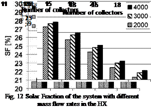 |
Since only part of the return fluid stream of the chilled water is cooled by the solar driven absorption chiller, the influence of the system performance of the quantity of this mass flow rate was investigated. Because the mass flow on the “cold side” was more or less fixed due to the flow rate required by the absorption chiller only the “hot side” flow rate, which is the side of the chilled water of the existing system, was changed. Three different mass flow rates were simulated: 2000, 3000 and 4000 kg/h. Results are presented, in fig. 12 and fig. 13, for the systems with 2 m3 storage volume and varying number collectors. As expected the solar fraction SF as well as the total system performance increases with higher flow rates on the “hot side” of the heat exchanger (see fig. 12).
This is because the storage can be discharged faster (with larger temperature differences) in discharge mode. Moreover the chiller performs better in direct mode due to the higher inlet temperatures in the evaporator heat exchanger (i. e., less part load operation). Increasing the mass flow rate from 2000 kg/h to 4000 kg/h results in increment of about 1% of the solar fraction for a specified number of collectors, However, higher flow rate means larger pump, higher costs and
electricity consumption. And thus, a middle value of 3000 kg/h was selected as the flow rate for the cold side of the system.
The results show a tendency of over prediction of the energy going out of the storage tanks. This is mainly due to the model used for the storage tanks which simulates the “ideal case” in order to maintain the stratification in the tank (the hot water coming from the collectors goes in the layer with the similar temperature). In reality, the hot water enters in a fixed inlet in the middle of the first tank which limits the stratification in the tanks. The temperature at the top of the first tank (to supply) is therefore smaller than the simulated one, which explains the difference with simulated values. This problem can be solved by using another type of tank model using fixed inlet positions.
2.2. Adsorption chillers
Table 3 summarizes the different cases simulated and compares the measured and simulated results in terms of mean cooling power and COP of the chillers defined by equations (2) and (3).
n is the number of time steps in the considered period i is the considered time step.
|
Table 3: Summary of the measured and simulated results for one of the adsorption chiller
|
NB: The operating conditions for the two others water circuits (chilled and recooling) can be seen on the figures 5-8.
The results show good agreement between simulation and measurements for the different operating conditions studied. Therefore the model will be used for further investigations.
3.1. Solar desiccant cooling parametric analysis
A number of simulations were performed, for the Sydney climate, with heat provided from an unboosted flat-plate solar heat source. Based on simulations performed at constant desiccant regeneration temperature, a desiccant cooled air flowrate of 3.71 airchanges per hour was initially selected. Three solar collector sizes were examined ranging from 500m2 (0.167m2 of collector/m2 of conditioned floor space) to 1500m2 (0.5m2 of collector/m2 of conditioned floor space). The lowest (500m2) collector area simulated is similar to that suggested by Henning [6] being approximately 3 m2 of collector/kW of cooling.
Figure 4 illustrates the impact of target zone temperature and collector area on the number of hours per year that the zone temperature exceeds the target. While Figure 4 confirms that increasing collector area successfully reduces the frequency of high temperature events, the number of high temperature events is still higher than that normally expected for satisfactory comfort conditions. From a capital cost perspective, it is also unattractive to use large collector areas.
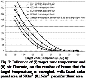
In an attempt to further reduce the frequency of high temperature events, the impact of increasing air flowrate was examined at a constant collector area of 500m2 (0.167m2 of collector/m2 of conditioned floor space). Results of these simulations are presented in Figure 5.
 |
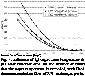 |
Figure 5 highlights a decrease in the frequency of high temperature events when supply airflow is increased. However, the concomitant increase in regeneration airflow will cause the regeneration air temperature to decrease. Further examination of the 6.18 airchanges per hour solar desiccant cooling simulation results found that the average temperature of the regeneration air during solar cooling was 40.7°C, which is at the lower limit of the range where the psychrometric model of Beccali et. al. [3] is applicable.
The use of high air flowrates also cools down the solar heated hot water faster. Consequently, the pump supplying hot water to the heating coil is stopped earlier in the afternoon and there are fewer hours of active solar cooling. It would appear that the reduction in frequency of high temperature events, at higher air flowrates, is more to do with an increase in the amount of cooling through conventional evaporative airconditioning than from increased performance of the desiccant cooling process itself.
To test the relative contribution of the desiccant dehumidification step, compared to the evaporative cooling effect, an additional set of simulations was performed using a standalone two stage indirect and direct evaporative cooling process (without dehumidification). Results of the evaporative cooling only simulations are also presented in Figure 5. Comparison of results with and without the solar desiccant dehumidification step suggest that the solar desiccant dehumidification step is effective at reducing the number of hours at which zone temperature exceeds 23°C, but conventional evaporative cooling is the dominant mechanism for eliminating the small number of highest temperature events.
Closer examination of the highest temperature events found that the pump supplying hot water to the heating coil was generally switched off during these periods, either because the hot water tank had never reached temperature that day, or because the temperature in the hot water tank had dropped below the thermostat set point in the afternoon. This result suggests that it may also be desirable to explore the potential of altering the control strategy and/or temperature set points, with the aim of keeping the hot water supply pump running for longer.
As many studies highlight [5-9], to implement one adequate configuration and control system on a solar cooling installation, can vary importantly the performance of this facility.
With regard to the control of absorption chillers, [10,11] demonstrate the need to control the chiller by means of the temperature or the generator flow, affecting to the performance as well as to the load capacity.
Described below are the basic controls considered, that later will be applied to the different configurations studied for the installation.
2.1. Starting criterions for the solar pump
Start based on differential temperature.
The starting signal for the pump is given in function of the difference between the temperature of the lower part of the tank and the one at the collectors output. Is associated to controls on-off.
Start based on constant radiation.
The pump starts when is reached a value for the global radiation higher than a threshold. This kind of criterion does not take into account the particular conditions in which the installation is in each moment what force to set thresholds relatively low, and this make the pumps to work more time than the necessary. This strategy has not been implemented on the simulation.
Start based on critical radiation.
The critical radiation [12], allows to calculate the needed value of the radiation to reach a fixed average temperature on the collector, depending on its parameters and the ambient temperature. It has been developed a controller that calculates the critical radiation and start up the installation when this value is exceeded.
W. Sparber1*, A. Thuer2, F. Besana1, W. Streicher3, H. M. Henning4
1 EURAC Research, Institute of Renewable Energies, Viale Druso 1, 39100 Bolzano, Italy
2 AEE INTEC, Feldgasse 19, A-8200 Gleisdorf
3 TU Graz, IWT, Infeldgasse 25/B, A-8010 Graz
4 Fraunhofer ISE, Haidenhofstrasse 2, D — 79110 Freiburg im Breisgau * Corresponding Author, wolfram. sparber@eurac. edu Abstract
In the present paper a monitoring procedure for Solar assisted Heating and Cooling (SHC) systems is presented. The procedure is subdivided in three different levels of complexity, allowing a first evaluation with a limited set of sensors or a precise evaluation with a full monitoring system. The procedure has been elaborated within a project of the International Energy Agency. The application of the procedure should allow a direct comparison of the functioning of different solar cooling systems and of simulation results. Further information can be found as well on the related task homepage [5].
Keywords: Solar heating and cooling, monitoring procedure, performance assessment
Monitoring of installed solar assisted cooling systems represents a fundamental tool in order not only to optimise the monitored system it self, but as well to draw conclusions for the optimisation of the design and control for future installations. This is especially true for a technology in an early stage of market penetration as it is the case for solar assisted cooling systems. In fact today, to the knowledge of the authors, only around 300 solar assisted cooling systems are installed world wide, and most of these show different designs and surrounding conditions [1][2][3].
In order to allow a clear comparison between monitoring results of different installed systems, and as well between measured and simulated values, a comprehensive and unified monitoring procedure is required.
The purpose of the present work is the presentation of such a monitoring procedure which has been developed within the frame of the international perennial years project — Task 38 — under the umbrella of the International Energy Agency (IEA) Solar Heating and Cooling Program [5].
Within Task 38 in the years 2008 and 2009 14 small scale (< 20 kW cooling capacity) and 12 large scale systems are planned to be monitored. The procedure should not be restricted to the IEA activities and the mentioned systems but support future monitoring activities in general.
For the elaboration of the monitoring procedure several boundary conditions have been considered. On one hand the procedure defines minimum requirements to be respected by all running monitoring projects, on the other hand detailed data and single energy flows should be measured where feasible in order to acquire a possibly complete picture of the functioning and to allow detailed analysis. The procedure should allow a comparison between different systems and as well permit to draw (with the results) a learning curve over the coming years on the cost development of installed solar assisted heating and cooling systems.
In order to respect these requirements a three step monitoring procedure will be presented in the following, differing in level of detail, necessary hardware, measured data and complexity. DEC systems are included only in the third level calculation
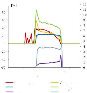
In order to have a common starting point for the single monitoring levels a basic scheme and a reference system had to be defined. In the following Figure 1 and Figure 2 the proposed reference solar assisted heating and cooling (SHC) system including the detailed energy fluxes for full monitoring and the conventional reference system are shown:
|
|
|
|
|
|

 |
|
(g) Pimp 6 «№oirt 617
Q… Hoot «CW
E… ………. if ритрь fan, г x…
Figure 2. Proposed schematics of the conventional reference systems including the single energy fluxes
|
Condensor; 22 kW
Figure 1: Sketch showing AC-Sun used on an A/C-plant |
The AC-Sun devise consists of a traditional thermal solar panel using water with temperatures between 75-95°C. An expander, based on a Rankine-process, uses the energy from solar panels to operate a compressor, which through a Carnot-process cools air in traditional air coolers:
The system only uses water as the cooling medium and there is therefore no source of pollution. The principle is to make vacuum in a small tank and thereby lowering the temperature on the water used to cool the evaporator.
A normal thermal solar collector makes hot water at a temperature from 75 to 95°C. This temperature range is very low but can be used as direct energy to the A/C-system in AC-Sun. The cooling system works all together without any use of electrical energy. The only electrical parts of the system are the ventilators and two small water pumps. Totally electrical energy used in AC-Sun is only 10% on normal A/C consumption.
10th October, Lisbon — Portugal /
![image445 Подпись: Ideal Rankine / Carnot cycle with reheating s [kJ/kg-K] Figure 2: Ideal Rankine / Camot cycle with reheating](/img/1154/image445.gif) The process uses water as cooling agents both in the expander and the compressor and therefore is environment friendly. The challenge comes from the use of water as a process agent. This means that the expander must be overheated minimum between 60- 80°C, as well as processing must be in two steps.
The process uses water as cooling agents both in the expander and the compressor and therefore is environment friendly. The challenge comes from the use of water as a process agent. This means that the expander must be overheated minimum between 60- 80°C, as well as processing must be in two steps.
The water steam from the vacuum tank is compressed in a small compressor like a turbo compressor on a car. The power to the turbo compressor comes from an expander connected to the solar collector.
The expander and compressor works on the same spindle shaft. Energy from the solar collector makes the rotation on the expander which drives the compressor.
The hurdle is the temperature in the expander — the steam making the expander to rotate has to be overheated so the steam doesn’t condense at the end of the expander blade. If this occurs at working speed, the lifetime for the turbine blade will be told in hours/days because of possible cavitations on the surface of the blade and later devastating the structure in the material.
The “temperature-help” comes from the compressor. The steam produced in the evaporator gets compressed and the temperature rises to at least 230°C in the compressor outlet. Through a small heat exchanger the energy from the compressor outlet goes to the expander inlet making the expansion possible without cavitations. The cooling and heating process is illustrated in a log PH-diagram showing the expansion and compression.
In principle this will cause AC-Sun turning 1.0 kW heat from 0.8 to 1.0 kW cooling. Other processes have an energy efficiency value less than half this size. And the production prices for those plants are — in contrast to AC-Sun — significantly higher than the A/C market price. The energy transformation in the AC-Sun is 1.5 kW at 10 kW cooling capacity and can with higher inlet temperature make electrical energy in a generator. In addition it’s possible to draw sterile water from the system — it has only to be supplied with the same amount of untreated water.
Maximum capacity on AC-Sun occurs after noon when the sun heats the most and the plant is controlled by a simple electrical system with low energy consumption.
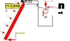
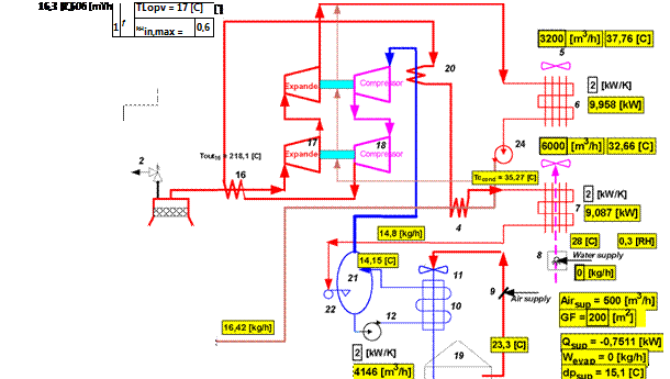
The pipeline layout including certain KEY-numbers is seen in figure 4.
The system has been modelled in EES [1] with the adequate thermodynamic equations giving the performance of the system under specific conditions.
![]()
 |
 |
Furthermore the EES is in the process of being integrated in a TRNSYS [2] model, which will be used to estimate the yearly performance of the systems under different climates, as well as to optimise the dimensions etc. of the overall system.
The AC-Sun is planned to be produced in unit sizes with a 10 kW cooling capacity each. Each unit can be mounted together to make a larger cooling capacity, multiplying numbers of AC — Sun units to satisfy the needs for air condition.
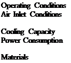 TOutside from 25°C to 45°C at 100% humidity
TInlet from 16°C to 24°C
Maintaining fixed temperature
10 kW each unit
Fans and pumps = 0.4 kW
10% on normal A/C consumption of electricity
Turbine: aluminum, cast aluminum, stainless steel
All other materials has a format like traditional air condition plants

 |
12 kW capacity at TSun from 75°C to 95°C
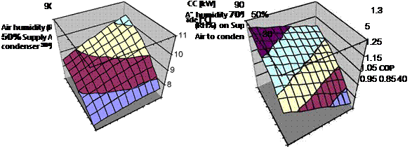
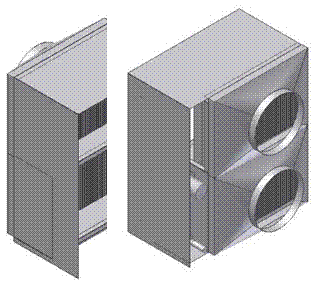
Figure 5: A/C-unit using AC-Sun — Dim 1,2×0.8×0.6 [m] without solar collector Cooling capacity / Coefficient of Performance
Figure 6: COP
The cooling capacity, fig. 5, depends partly on the condenser efficiency. This efficiency can be changed by spaying water in the air to the condenser and thereby raise the air humidity in the supply air.
M. Zetzsche1), T. Koller1), H. Mtiller-Steinhagen^ 2)
1 University of Stuttgart, Institute of Thermodynamics and Thermal Engineering
Pfaffenwaldring 6, D-70550 Stuttgart, Germany
Tel.: 0049-711-685-63230, Fax: 0049-711-685-63503
E-Mail: zetzsche@itw. uni-stuttgart. de
2) Institute of Technical Thermodynamics, German Aerospace Center (DLR)
Abstract
The Institute for Thermodynamics and Thermal Engineering of the University of Stuttgart (Germany) is developing a solar-driven cooling system based on an ammonia/water absorption chiller. In addition to the cooling engine itself, a concept for the cooling of buildings has been realized. Essential parts of this concept are the building with chilled ceilings, an ice storage and the absorption chiller which works with a dry cooling system. Following a period of intensive testing and analysis of the performance, the chiller will now be operated under practical conditions. Therefore, five rooms of the department’s building have been equipped with chilled ceilings and are connected to the solar-driven chiller unit.
In the present paper, operational details of the chiller and the general cooling concept will be presented. Additionally, the combination of the chiller with the dry cooling system, the solar collectors and the ice storage will be discussed. Charging and discharging of the ice storage play an important role for covering the cooling load at any time. All components are controlled with an SPS (stored program control) control unit. Measurement data such cooling power, thermal comfort in the rooms, COP of the absorption chiller with boundary conditions like cooling temperatures and solar radiation are presented. The quality of the supply with cooling energy is part of this paper.
Keywords: solar cooling, absorption chiller, ammonia water, ice storage, chilled ceiling
1. Introduction
The ITW-absorption chiller has a cooling capacity of 10 kW at standard conditions (14 °C chilled water outlet, 27 °C cooling water inlet, 100 °C hot water inlet, COP 0,72) [1]. The working fluids are ammonia and water. For heat rejection a dry cooling tower is used. As heat source flat plate
 |
|
 |
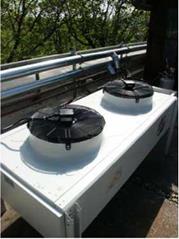 |
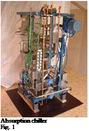
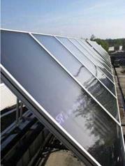
collectors with a high efficiency are applied. The main components are shown in the following figures.
Flat plate collector (32 m2) Dry cooling tower Components of ITW-solar cooling system
Four offices and one meeting room of the department’s building are equipped with chilled ceilings. The total area of all rooms amounts to 115 m2. In each office 3 persons are working. The offices are usually occupied from 8 a. m. to 17 p. m.. The occupation of the meeting room is variable. During the measurements the meeting room was not occupied, nevertheless it was cooled. The orientation of the windows in the rooms is east and the solar collectors are orientated to the south. In addition to the chiller an ice storage is installed. This storage was developed parallel to the development of the ammonia/water chiller. It was measured and tested with several heat exchangers [2]. The storage tank has a volume of 500 litres and an amount of ice of 300 kg can be produced. This corresponds to a cooling capacity of 35 kWh.
The ice storage is charged by the chiller and can be used as a back-up system or an extension to cool the rooms.
Figure 2 shows a schematic lay-out of the piping of the components.
Two heat-exchangers are installed to transfer the cooling energy from the chiller or from the ice storage to the rooms. The ice storage is discharged by external melting of the ice. This means that the water in the ice-storage is directly used in the heat exchanger.
In every room the complete ceiling is covered with metal cooling panels. When using chilled ceilings it is important to control the inlet water temperature into the rooms. Condensation of the ambient air on the chilled ceiling must be avoided. Additional to the control of the forerun
temperature, a sensor for relative humidity is installed in every room. When the dew point is reached, the sensor provides a signal to the controller and the flow through the chilled ceiling of this particular room is stopped.
|
|
Other than the ice storage, no other thermal storage facilities are installed. One special feature of the ITW chiller is that the heating temperature has not to be controlled. The heating temperature depends on the thermodynamic equilibrium of the solution in the generator. The evaporation in the generator starts when a certain temperature level, which depends on the concentration of the ammonia in solution, is reached. If the required temperature level is not available, the outlet temperature of the generator is almost equal to the inlet temperature. Hence, the collector cycle is heated up until the required temperature level is available. Then the absorption cycle starts to work.
The main influence on the required temperature level is the concentration of ammonia in the strong solution. This concentration depends on the cooling temperature of the absorber.
The chiller unit is controlled by an SPS (Stored Program Control). The SPS unit switches all of the pumps and the dry cooling tower on and off. Internal valves are regulated in such a way that the COP is always at maximum. Of course, the maximum COP depends on the boundary conditions when the chiller is running. These boundary conditions, like hot water temperature, recooling temperature and cold water temperature, are taken into account for the control process. When COP is an maximum the cooling power will be also at the maximum (1).
The available cooling power must be used as efficient as possible, either to cool the rooms or to store the cold energy in the ice storage. Therefore several control strategies have been developed. The control of the system is adapted to the climatic conditions and the cooling load in the rooms. It is intended to cover with this system the cooling demand all the time when the rooms are occupied. Therefore the system may be operated in five different states:
(1) Direct cooling of the rooms. Cooling energy is transferred with heat exchanger no. 1.
(2) Producing ice, if no room cooling is needed (e. g. on weekends).
(3) Cooling the rooms and producing ice at the same time. The storage is charged and discharged simultaneously. The cooling energy is transferred with heat exchanger no.2. In this case the cooling capacity of the rooms has to be lower than the cooling performance of the chiller when producing ice at 0°C to -10°C.
(4) Discharging the ice storage when the chiller is out of operation (e. g. in the morning, at night, etc.)
(5) Supporting the performance of the chiller by simultaneously discharging the ice storage. In this case, peak demands can be covered or cooling energy can be supplied when the sky is cloudy and the solar gains are low.
In every room a sensor for air temperature and relative humidity has been installed to evaluate the thermal comfort. Furthermore temperature sensors (thermocouples) are fitted to every inlet and outlet of heat exchanger no. 1 and no. 2. The flow through these heat exchangers is measured as
well as in the chilled ceiling circuit. The measurements for the operational states (1) and (2) are presented in the following chapters.