Как выбрать гостиницу для кошек
14 декабря, 2021
D. B. Riffel*, F. A. Belo and A. P. F. Leite
Solar Energy Laboratory, Federal University of Paraiba, 58051-970, Joao Pessoa, Brazil
Corresponding Author, dougbr@gmx. net
Abstract
This paper presents the design optimization of an adsorber using a statistical modelling. The energy equations for the adsorber were formulated and its results were introduced in the statistical modelling. Fin-tube heat exchangers were chosen for adsorption beds in order to improve the heat transfer rate. The adsorber here designed is the main component of a 20 kW chiller, which runs mainly on solar energy, with a complementary heat provided by gas. Cold water is produced during night-time in an activated carbon-methanol adsorption chiller and then stored in a tank in order to supply cooled air during day-time. Solar energy is used for regenerating the adsorbent medium by means of highly efficient flat-plate collectors. Thermal energy is stored in a hot-water tank so as to supply the chiller at night. This air conditioning unit is designed to provide thermal comfort to four adjoined laboratory rooms, whose total area is 110m2. The optimized adsorber was obtained for the following values: the hot water temperature of 100 °C with 0.8 kg/s, the cycle period of 40 minutes, 56 tubes and 100 cooper fins of 0.5 mm.
It results in a COP of 0.52 and SCP of 51 W/kg.
Keywords: adsorption, solar cooling, optimization, statistical modelling, simulation
Solar cooling is an interesting application of solar energy because, the stranger the irradiance, the greater needs for cooling. As a rule, the systems requiring thermal energy as their main power input for generating cooling effect are most dependable on sorption processes. This energy may come from different sources, such as: process heat, residual vapour or solar energy. One of the main advantages of such a system in relation to the conventional vapour compression system lies on its minimum use of electric energy and on its low cost of maintenance.
In the last two decades, absorption chillers, running on natural gas, have been introduced in markets all over the developed world — in the US, Japan, France, Italy, Spain and more recently in Portugal. As to adsorption systems — in spite of several studies that demonstrate their technical feasibilities -, there exist only experimental units, though stand considerable chances of becoming economically viable, especially where thermal comfort applications are concerned.
This paper presents the design optimization of an adsorber, as part of a chiller of a solar/gas air conditioning system, using a statistical modelling. The energy equations for the adsorber were formulated and its results were introduced in the statistical modelling. Plate-fin heat exchangers were chosen for adsorption beds in order to improve the heat transfer rate, increasing the contact area with the adsorbent. Cold water is produced during night-time in an activated carbon-methanol adsorption
chiller and then stored into a tank in order to supply cooling air during day-time. Solar energy is used for regenerating the adsorbent medium by means of highly efficient flat-plate collectors. Thermal energy is stored in a hot-water tank so as to supply the chiller at night. This air conditioning unit is designed to provide thermal comfort to four adjoined laboratory rooms, whose total area is 110m2. Details of this unit can be found in [1].
The office building of field test is located in Hamamatsu, the central part of Japan, where both space heating and cooling are necessary. Figure 2 shows the exterior view of the field test building and the interior view of the field test space provided with the building integrated solar thermal
system built in 2007. This office building is almost faced to South (Azimuth : 10 degrees to East). The roof with the integrated collector is tilted at 17 degrees. Two parts of the solar collection area is on the roof. Each solar collection area has the solar collector covered glasses of 60m2 and the
|
Fig. 5. Schematic diagram of solar desiccant cooling system in the field test building. |
solar collector without glasses of 30m2. Two set of the solar desiccant cooling system are respectively installed in the attic space below the roof of the solar collection area. The office building is two stored with the total floor area of 1,560m2. The field test space is the office space and the civic hall of the ground floor with the floor area of 400m2 as shown in Figure 2. In addition, electric heat pump air conditioning units (EHP) are used for space cooling in summer and space heating in winter. The EHP is designed to be used only for processing the room heat load, because the solar thermal system processes the fresh air heat load. In summer, the high COP of the EHP is expected, because the latent cooling load is processed by the solar desiccant cooling system and the EHP has to process the sensible cooling load only. The monitoring period is a year from April,
2007 to March, 2008.
The state-of-the-art investigation proved that a large market is not yet reached actually. This is due to the high price of the technology. The state-of-the-art has shown that the technology is not yet embedded in the most energy effective places or in the most promising buildings.
Therefore, the existing solar cooling plants show a high cost reduction potential for next generation of solar cooling plants resulting from application on most promising buildings, lower prices of the main components (chillers, solar collectors), proper system configuration, well trained designer, installer and maintenance responsible people.
3.1 Conclusions of high-potential building sectors and applications
The conclusions of the analysis of for most promising cases with absorption systems are the following:
— The EU country with most cases of low costs of primary energy savings is Spain. Esfahan has also a very promising situation. In both cases the availability of solar irradiation as well as the combination of cooling and heating demand is very favourable for a good performance of the solar cooling plants. Besides that, the case of Esfahan has the advantage of low prices of gas. Mexico has similar cases to others in Spain or Esfahan. The other EU country, ordering by criteria of the most promising opportunities for cost reduction, is France, with cases very similar to the ones in Spain, and finally, Austria, where the cost of primary energy savings mainly take the higher values.
— In spite of this general conclusion, some cases have lower costs in France than in Spain, for instance a hotel in Lyon-B3 than a office in Madrid-C1. It means that in some cases, the influence of daily and monthly profile of the demand has more influence than the solar irradiation on the performance and economic results of a solar cooling plant.
— By ordering the results from the minimum to the maximum value for costs of primary energy savings per each country, the different cases have been nearly ordered in groups by the type of building. This shows that the cases with low costs of primary energy savings are hospitals
and hotels. Those are followed by offices and trade centres. Finally, the most unfavourable cases are residential. The table 4 shows the cases with lower value of this parameter, that varies between 0.11 and 0.14 €/kWh_PE, with primary energy savings between 15 % and 25 %.
|
name |
PE savings |
Cost PE unit |
|
ESPmalagaA1V |
21% |
0.11 |
|
ESPmalagaA3N |
24% |
0.11 |
|
WesfahanA3N |
19% |
0.11 |
|
E SPm adridA3N |
19% |
0.12 |
|
WesfahanB4N |
20% |
0.13 |
|
ESPbarcelonaA2M |
18% |
0.14 |
|
ESPmadridB4N |
17% |
0.14 |
|
ESPmadridA1V |
15% |
0.14 |
|
ESPmadridB2N |
20% |
0.14 |
|
FRAperpignanB3V |
17% |
0.14 |
|
table 4. Most promising cases for costs reduction of solar cooling systems AB+FPC |
The conclusions of the analysis of for most promising cases with desiccant systems are the following:
— The level of costs of primary energy savings is much lower in the analyses cases with desiccant technology than with absorption technology, therefore the values range here from <0,04 €/kWh_PE to >0,12 €/kWh_PE.
— By ordering the results from the minimum to the maximum value for costs of primary energy savings per each country, the different cases also have been ordered nearly in groups by the type of building. This shows that the cases with low costs of primary energy savings are hospitals and hotels. Those are followed by trade centres and offices. The table 5 shows the cases with lower value of this parameter, that varies between 0.01 and 0.03 €/kWh_PE, with primary energy savings between 19 % and 40 %. The best case here is the hospital in Malaga (VEE) with 40% primary energy savings by only costs of primary energy savings of 0,01 €/kWh PE.
|
name |
PE savings |
Cost PE unit |
|
AUgrazA1V |
19% |
0.01 |
|
AUviennaA1V |
21% |
0.01 |
|
AUgrazB4N |
21% |
0.02 |
|
AUgrazB3V |
22% |
0.02 |
|
AUviennaB4N |
21% |
0.02 |
|
AUviennaB3V |
23% |
0.02 |
|
FRperpignanB3V |
33% |
0.01 |
|
FRperpignanA1V |
33% |
0.02 |
|
FRlyonB3V |
25% |
0.03 |
|
FRnantesA1V |
26% |
0.03 |
|
ESPmadridA1V |
37% |
0.01 |
|
ESPmalagaA1V |
40% |
0.01 |
|
ESPbilbaoA1V |
27% |
0.02 |
|
table 5. Most promising cases for costs reduction of solar cooling systems DEC+FPC 3.3 Conclusions of RTD Gaps, Potentials and Topics |
Concerning the ideal specification for components it can be concluded that there are some significant technical specification related to solar-assisted cooling which are not taken into account in the existing installations. These specifications lead to a better energy performance of the whole system and are in some cases obligatory to achieve high energy saving ratios in comparison to conventional cooling systems (e. g. cooling tower, air-conditioning devices).
The technological gaps refer besides the necessary technological improvement of each component also to the requirements for better system integration of each part of the solar — assisted cooling system. To solve the gap of reliability the focus on improved control systems as well as design and engineering will be important in the future.
The cost reduction potential of each single component of solar-assisted cooling systems ranges from 2-15% using feasible short-term and medium-term technology development scenarios. The highest influence on cost reduction of the whole system has the solar collector field with 15% by cost reduction of 30%. To get a cost-competitive situation of solar-assisted cooling systems towards conventional systems two cases would have the highest influence: increase in energy prices and subsidies.
For thermally driven chillers (absorption, adsorption) the efforts for cost reduction must be very strong in each part of the system and the frame conditions as energy prices and subsidies must improve, otherwise for short-term and medium-term a cost-competitiveness of that technology in comparison to conventional cooling can not be achieved. The cost situation of desiccant evaporative cooling systems is much better; here the generally limited field of application on air-based cooling systems and a lack of reliability due to gaps in sophisticated control systems, engineering and maintenance seem to be the main barriers for market penetration.
The expert workshops for market penetration made clear that a lot of tasks are necessary to do, not only on technology development, but also on customer-specific preparation of the whole topic by setting up information material, realisation of demonstration sites and getting package solutions. The supplier of the solar-assisted cooling plants which are mainly engineering consultants and executive companies will also need support by training, pre-selection tools, planning tools, pre-defined control strategies and monitoring data of running installations. Besides solar-assisted cooling, there are also some other sustainable cooling technologies in the market as passive cooling, geothermal usage, biomass and district cooling. It has to be evaluated in a proper way by a comparison of technologies, which positions solar-assisted cooling could have in the rapid rising cooling demand in buildings. A roadmap for solar — assisted cooling systems on national levels and on European level should be one of the next tasks in that field. The future topics in the field of solar-assisted cooling will have a very big range from technology development and demonstration sites to market implementation activities, training and dissemination.
Partners in ROCOCO project are:
— ARSENAL RESEARCH, Austrian independent public research company in the field of renewable energy, www. arsenal. ac. at
AIGUASOL, planning and consultancy private company in the field of energy efficiency and particularly solar energy, www. aiguasol. com
— CONNESS, Austrian consulting and project planning company with focus on renewable energy and energy efficiency, www. conness. at
— GMI, Austrian planning and realization of building-climatic concepts company, www. teamgmi. at
— TECSOL, French technical engineering and project management office specialized in solar energy for buildings, www. tecsol. fr
— FOTOTERM, Spanish solar thermal system installer, www. fototerm. com
— HSF, French air-cooling/heating system and hydraulic equipment installation, management and maintenance company for buildings and industry, www. stihle-freres. fr
![]() Absorption
Absorption
Adsorption
Desiccant Evaporative Cooling technology
Domestic Hot Water
Flat plate collectors
Evacuated tube collector
Flat plate collectors
Primary Energy
Reference
Research and Technology Development Solar-assisted Cooling Total Annualized Cost Technology and Market sector
[1] TRNSYS, Transient System Simulation Program, Solar Energy Laboratory, University of Wisconsin Madison, Version 15.09, 2001
It was mentioned that for night cooling a strategy based on a combination of radiative cooling and natural ventilation was employed. At night, when climatic conditions are favourable (i. e., when ambient temperature is low enough to provide a cooling effect), water is circulated in order to exchange energy between the radiant floors and the radiative panels so that the floor temperature can be brought down and the zone heat gains be dissipated. In the meantime, the motorized dampers in the office zones open to enable night cooling by means of cross flow natural ventilation driven by a set of solar chimneys. In automatic mode, both systems work together depending on schedules and temperature setpoints, but users with supervisor privileges in the SCADA system can manually activate or deactivate any of the systems. Night cooling supposedly works until the early morning, while the ambient temperature and solar radiation are still low enough for natural ventilation and radiative cooling to maintain an adequate thermal comfort inside the building without the need of any active system. However, the weather tends to get warm very quickly in the morning in Almeria so that active cooling system may be required quite soon for indoor conditions to remain acceptable. Nevertheless, it is important to mention that passive cooling techniques always have the priority over other cooling techniques and are used whenever possible in order to minimize energy consumption associated with the operation of the building’s air conditioning systems.
Another interesting alternative to the standard DEC system is shown in Fig. 4. In this configuration, dehumidification is performed in two different stages; the first stage is carried out by means of an enthalpy wheel, which is similar to the recovery wheel, but in which latent heat can also be exchanged, thanks to the adsorbent materials which cover the rotor surface. Thanks to the enthalpy wheel, a certain amount of water vapour is transferred from the process air to the exhaust air, thus avoiding the use of a pre-cooling coil; but the most important consequence is the need of a lower regeneration temperature, which in this case reduces to 61 °C, given the same inlet conditions for the supply air (point I in Fig. 4). This means that both the cooling and the heating power required by the air-handling unit reduce, allowing important improvements on energy savings and exergy performance, as shown in Fig. 5, where the comparison is made with the standard DEC system working with Treg = 70°C.
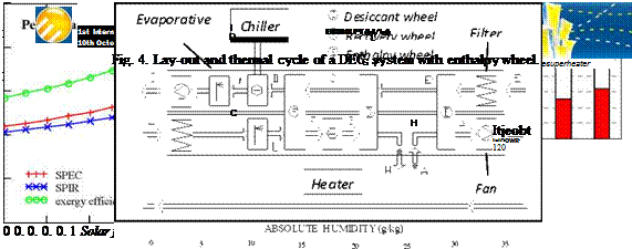 |
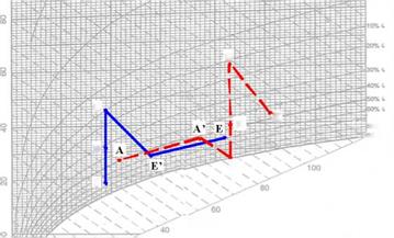 Fig. 5. Improvements due to the adoption of an enthalpy wheel
The most relevant results refer to the exergy efficiency, and are mainly due to the consistent reduction of the cooling power, which is produced through the use of electric energy, characterized by very high exergy content. The adoption of this solution also emphasizes the advantage of using solar energy to assist regeneration, as the performance improvement gets higher for high solar fractions.
As shown in the previous paragraphs, it is possible to improve the energy and exergy performance of a standard DEC system by adopting some additional components which allow relevant energy recovery.
 |
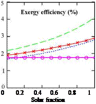 |
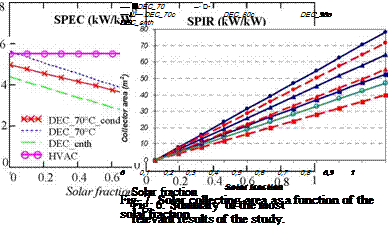
Fig.6 summarizes the most important results, and underlines the great advantage of using the solution with an enthalpy recovery wheel. For a right interpretation of the results it is necessary to look at Fig. 7, as a certain solar fraction corresponds to different collecting surface according to the system which is considered; indeed, the entity of the thermal power required by the heating coil depends on the plant scheme. This is an aspect which can not be neglected, especially if the first and second law results of this study must be translated in economic figures. In terms of collecting surface, the results are shown in Fig. 7; they refer to vacuum tube solar collectors and an overall irradiation as high as 800 W/m2.
[1] G. Evola, L. Marietta, F. Sicurella, Energy and Environmental Performance of Solar-assisted Desiccant Ventilation Units: a Life-cycle Perspective, CLIMAMED International Conference, Genoa, 2007.
[2] Daou K., Wang R. Z., Xia Z. Z., Desiccant cooling air conditioning: a review. Renewable & Sustainable Energy Reviews 10 (2006), pp. 55-77.
[3] Mazzei P., Minichiello F., Palma D. HVAC dehumidification systems for thermal comfort: a critical review. Applied Thermal Engineering 25 (2005), pp. 677-707.
[4] G. Evola, L. Marietta, F. Sicurella, Second law analysis of solar-assisted desiccant open cycles: a comparative analysis, 2nd International Conference on Solar Air-conditioning, Tarragona, 2007
[5] A. Bejan, Advanced Engineering Thermodynamics. New York: John Wiley & Sons, 1988.
[6] W. J. Wepfer, R. A. Gaggioli, E. F. Obert. Proper evaluation of available energy for HVAC. Ashrae Transactions 85 (1979), pp. 214-230.
In 1974 Nobel Prize winners Rowland and Molina proposed that chlorofluorocarbons were stable enough to reach the stratosphere, where, under intense solar radiation they released chlorine atoms that could destroy stratospheric ozone layer protecting the earth’s surface from UV rays. This was confirmed by an extensive worldwide program that aimed at monitoring the ozone layer. As a consequence, a series of national and international agreements calling for the phase-out of the production, sale and use of ozone depleting substances such as chlorofluorocarbons (CFCs) and hydrochlorofluorocarbons (HCFCs) [3] were formulated. Another major environmental concern is the climate change also called global warming. Our planet is already facing the consequences of this phenomenon: polar ice caps melting, flooding from high precipitations, increase of the earth global mean surface temperature, plants and birds migration towards the poles, etc. The increasing awareness conducted to the Kyoto Protocol in 1997 [11]. The impact of a substance on the environment is characterized by parameters like ozone depletion potential (ODP), global warming potential (GWP), atmospheric lifetime (ALT). Table 1 lists environmental data for potential ORC working fluids. For the sake of a safety environment, the designers when selecting a working fluid for a particular application should insist on substances for which the ODP, GWP and ALT are as low as possible.
Two demonstration subprojects (Demo SP6a and Demo SP6b), among a total number of 12 in Polysmart project, are implemented in Portugal. Their description as well as the main differences between them is presented below.
3.1. Main characteristics of Demo SP6a
Subproject SP6a is designed to condition (heating and cooling) some office rooms (175 m2) equipped with fan coils at Ao Sol’s two-storey office building, and to heat up a DHW tank (0,4 m3) for the lavatory (showers included). A showroom (50m2) equipped with a small radiant floor as well as two fan coils (4-pipe distribution system) will also be supplied by the CHCP plant whenever needed during guided visits.
3.1.1. Functional Block Diagram and main Equipment
The two main parts of the Combined Heat Cool and Power system — pCHCP are the Combined Heat and Power unit — CHP (cogeneration) and the Thermally Driven Chiller unit (TDC).
The former is composed by a LPG fuelled, single-cylinder 4-stroke engine (approx. 580 cm3) which drives a 5.5 kWe nominal active power, water-cooled asynchronous generator [5]. Using this type of fuel, the standard CHP unit, operating at nominal conditions, has a thermal output of
around 12.5 kWth and the heat recovery circuit reaches a temperature of 84°C. Since this level of temperature is not high enough to drive the TDC at full capacity, the CHP unit is equipped with an additional condensing exhaust heat exchanger (condensing unit) that enables to further raise the TDC driving temperature to around 90 °C by recovering the heat from the flue gas (at around 150°C). Thus, in this particular case, the overall efficiency of the plant can rise to over 100% (in relation to LHV for the fuel used) depending on the environmental conditions and conditions of use.
The latter is an 8 kWcold ammonia/water prototype machine [6] with a nominal COP of 0.6 and direct air-cooling (no need for external heat rejection devices — cooling tower).
A hot water storage tank (1m3) is used as a buffer between the CHP and the TDC / heat sink. This buffer also allows modulating the water temperature of the heating distribution circuit, since the CHP has a fixed thermal output.
Since the return temperature from the TDC hot water circuit is higher than the maximum allowed inlet temperature of the CHP heat recovery circuit, the DHW tank can be heated up by the surplus heat trough an internal heat exchanger. Once the DHW is fully charged, an Emergency Heat Rejection unit (re-cooler) guaranties the inlet flow temperature, preventing the CHP from damage.
The chilled water circuit is not physically separated from the CHCP main circuit by any heat exchanger.
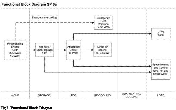 |
The following figure shows the functional block diagram of the pCHCP plant.
The system can also use solar energy as thermal input, both in winter and in summer. The collectors will be CPC AO SOL and 30m2 are already installed for this purpose. The objective is to measure the contributions of the different sources in different operating modes, analysing the results and proposing the best operational and integration procedures.
Both yearly heating and cooling loads and peak power demand have been estimated using TRNSYS simulation tool [7]. The goal is to select the zones to acclimatize that lead to an optimum operating period of the CHCP plant.
The conditioned area of the building is around 175 m2 and the yearly specific cooling load is estimated to be circa 25 kWh/m2.
Figure 7 shows that a rising regeneration temperature causes a sharp increase in exergy destruction and a drop in the exergetic efficiency. Regeneration at lower temperatures is favourable, which is also a well known fact for rotary type DEC systems. At higher regeneration temperature the temperature differences during the sensible heating and cooling stages are high, therefore increasing irreversibilities of the heat exchange. The decrease in exergetic efficiency is further due to an increase in exergy losses as the air leaving the heat exchanger during desorption is of a temperature significantly higher than ambient (fig. 2), thus of significant exergy content.
An improved system configuration would maximize the exergetic product and minimize exergy losses, increasing the exergetic efficiency. This could theoretically be realized a) during adsorption by further cooling the dehumidified process air (state 2) by an additional indirect evaporative cooler and b) during desorption by exploiting the exergy of the air leaving the sorptive heat exchanger for the preheating of the regeneration air. Simulations were performed for an enhanced system configuration including both improvement measures. The heat exchanger for heat recovery was characterized by an efficiency of 80% and simulations were performed for a regeneration temperature of Treg=60°C. Due to the lower resulting process outlet temperature T2 during adsorption the exergetic product can be increased by 17%, whereas due to pre-heating of regeneration air the exergetic input is decreased by 9% compared with the simple configuration at equivalent regeneration temperature. Therefore, the exergetic efficiency rises from 0.18 to 0.23, which is an increase by 28%. To put these values in perspective, the thermal COP, calculated as the ratio of removed heat to heat input during desorption, increases from 0.99 for the simple to 1.05 for the improved configuration. Due to the high COP values a good energetic performance is expected, but the exergetic assessment characterized by comparatively low exergetic efficiencies suggests that the improvement potential is still high. Detailed analysis of the exergetic performance for the individual cycle stages and the sub-processes evaporative cooling and adsorption/desorption is within the scope of future work.
Simulation results from a dynamic model of a sorptive heat exchanger were presented in an exergetic framework. Results show that the exergetic efficiency reaches a maximum at specific combinations of ambient temperature and humidity ratio, suggesting that the heat exchanger performs best in a certain range of climatic conditions. The exergetic performance is highest at low regeneration temperature, thus underlining the system’s good applicability with low grade heat. Further simulations showed that the exergetic efficiency can be increased by an enhanced system configuration comprising heat recovery during desorption and an additional indirect evaporative cooler.
[1] Motta, M., Henning, H.-M. (2005): A novel high efficient sorption system for air dehumidification (ECOS), International Sorption Heat Pump Conference, June 22-24, Denver, CO, USA.
[2] Schicktanz, M., Nunez, T. (2008): Modelling af an adsorption chiller for dynamic system simulation, International Sorption Heat Pump Conference, Seoul, Korea, September 2008, in press.
[3] Bosnjakovic, F. (1997): Technische Thermodynamik, Teil II, 6. Auflage, Steinkopf, Darmstadt.
[4] Szargut, J., Stryrylska, T. (1969): Die exergetische Analyse von Prozessen der feuchten Luft, Heizung, Lueftung, Haustechnik, 5, 173-178.
[5] Wepfer, W. J., Gaggioli, R. A., Obert, E. F.(1979): Proper evaluation of available energy for HVAC, ASHRAE Transactions, 667-677.
[6] Taufiq, B., Masjuki, H., Mahlia, T., Amalina, M., Faizul, M., Saidur, R. (2007): Exergy analysis of evaporative cooling for reducing energy use in a Malaysian building. Desalination, 209, 238-243.
[7] Chengqin, R., Ninping, L. Guanga, T. (2002): Principles of exergy analysis in HVAC and evaluation of evaporative cooling schemes. Building and Environment, 37, 1045-1055.
[8] Taufiq, B., Masjuki, H., Mahlia, T., Amalina, M., Faizul, M., Saidur, R. (2007): Exergy analysis of evaporative cooling for reducing energy use in a Malaysian building. Desalination, 209, 238-243.
[9] Kanoglu, M., Carpinlioglu, M., Yildirim, M. (2004): Energy and exergy analyses of an experimental open — cycle desiccant cooling system. Applied Thermal Engineering, 24, 919-932.
[10] Camargo, J., Ebinuma, C., Silveira, J. (2003): Thermoeconomic analysis of an evaporative desiccant air conditioning system. Applied Thermal Engineering, 23, 1537-1549.
|
Nomenclature |
Subscripts |
||||||
|
A |
area [m2] |
M |
molar mass [g/mol] |
a |
air |
sorp |
sorption |
|
c |
specific heat capacity [J/kgK] |
m |
mass [kg] |
D |
destruction |
v |
vapour |
|
E |
exergy [J] |
v |
specific volume [m3/kg] |
da |
dry air |
w |
water |
|
e |
specific exergy [J/mol, J/kg] |
e |
mass transfer coefficient [kg/Ns] |
evap |
evaporation |
0 |
reference state |
|
p |
pressure [Pa] |
n |
efficiency [1/100] |
ex |
exergetic |
1…4 |
state points |
|
R |
specific gas constant [J/molK] |
Ф |
relative humidity [%] |
mat |
material |
||
|
T |
temperature [K, °C] |
Ю |
humidity ratio [kg/kg] |
p |
constant pressure |
||
|
t |
time [s] |
sat |
saturation |
The project support of the German Federal Ministry of Economics and Technology and the support of the Reiner Lemoine Stiftung for the Ph. D. research of Constanze Bongs is gratefully acknowledged by the authors.
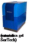
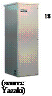
During the last few years especially in Europe many new small-scale sorption chillers have been developed. Many of these absorption and adsorption chillers have now passed from the prototype phase to field tests and into the production. Today absorption chillers with capacities from 4.5 kW to 30 kW and adsorption chillers with capacities from 7.5 kW to 15 kW cooling capacity are available [3]. Table 1 shows the different applications for the different chillers, the adsorber chillii® STC8 with a cooling capacity of 7.5 kW is mainly for residential buildings, the 12 kW ammonia/water absorption chiller chillii® PSC12 is for office buildings or process cooling like e. g. milk cooling and the 15 kW water/silica gel adsorber chillii® STC15 as well as the water/lithium bromide absorber chillii® WFC18 (17.5 kW cooling capacity) are for air-conditioning e. g. of office buildings, hotels, banks, bakeries, public and administration buildings.
|
0.79 x 1.06 x 0.94 m3 |

 |
 |
 |
 |

 |
||
 |
 |
|
 |
||
Table 1. Small-scale sorption chillers for solar cooling systems.
|
Dimensions (LxDxH)
|
 |
|||
![]()
![]()
 |
|
![]()
The fast predesign method for the selection and predesign of solar cooling systems in buildings is made of several steps which will be described in the following chapters. Some of them are didactic whereas others are more technical. The Figure 1 is aimed at presenting the structure with the different steps constituting the method.
Fig. 1. Structure of the method.