Как выбрать гостиницу для кошек
14 декабря, 2021
Thermal stagnation and risk for overheating is generally aimed to be avoided in any collector systems if these have metal-based — or polymeric collectors. The intention with a built-in overheating mechanism for polymeric collectors is to be able to use low-cost commodity plastics in glazed collectors.
High operational temperatures in polymeric collectors can be avoided by suitable hydraulic system design and dimensioning. Especially for solar combisystems with large collector areas the integration of the collectors into the facade reduces the risk for thermal stagnation during summer time.
At the same time it improves the performance during the heating season.
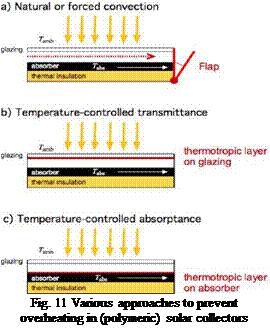
Natural or forced ventilation of the collector between absorber/glazing or absorber/thermal insulation can be used for the overheat protection of polymeric collectors. As illustrated in Fig. 11 (a) a flap is triggered by a temperature sensitive mechanism and opens when a critical temperature in the collector is reached, so that ambient air can ventilate and cool the collector [11, 12].
Functional materials / thermotropic coatings are a central topic in ‘Subtask C: Materials’ of IEA — SHC Task 39 and considerable R&D has been done, e. g. [13, 14, 15]: The principle is that the thermotropic coating switches from transparent to opaque at a critical temperature for the absorber material Tc. The coating can be applied on the glazing and reduces the transmittance (Fig. 11 (b)).or on the absorber and reduce the absorptance for temperatures above Tc (Fig. 11 (c)).

 |
Another principle for the overheat protection is proposed in the patent by Griessen and Slaman [16]. The refraction index of the collector glazing is changed by a simple mechanism and reduces the transmittance for solar radiation. The glazing is a prismatic structured optical layer, which is hollow inside. “The glazing is air-filled and transparent under normal operation but during stagnation filled with an appropriate fluid being totally reflective above the boiling point of the heat carrier in the absorber” [16].
Except for the first examples, the mechanisms for overheating protection are not commercial yet, but the R&D reveals the effort for making polymers with lower temperature resistance available for the use in glazed collectors.
1.1. Stagnation temperatures in reference — and ventilated collector (set-up A)
The measurements of the maximum temperatures in the reference — (Tr) and the ventilated collector (Tv) are shown in Fig. 2 for different days and tilt angles. The difference between these temperatures gives the reduction of the maximum temperature, which can be obtained by ventilating the solar collector. The maximum temperature reduction occurs during the warmest period of the day and lies in the present cases between approximately 20-30 K. Fig. 2 (a) and (b) display data from days with high solar irradiance. The collector tilt angle в was 45° for (a) and (b). The bottom slit aperture was 10 mm for (a). The maximum temperature of the ventilated collector, Tv, was slightly below 130 °C.
a) June 9, 2006 b) June 10, 2006 c) August 3, 2006
|
Tilt angle: 45°; slit aperture: 10 mm Tilt angle: 45°; slit aperture: 20 mm Tilt angle: 90°; slit aperture: 20 mm Fig. 2 Maximum temperatures in the ventilated (Tv) and reference collector (Tr) for different days and tilt angles; Im is the global solar irradiance, Ta the ambient temperature [set-up A]; |
For (b) the bottom slit aperture was extended to 20 mm and the maximum temperature Tv was slightly below 120 °C. In (c) the collector tilt angle was changed to 90° with a bottom slit aperture of 20 mm. Here a maximum temperature of Tv ~ 100 °C of the ventilated collector was measured.
![]() D. Fontani 1*, P. Sansoni 1, F. Francini 1, D. Jafrancesco 1, G. Chiani 2, M. De Lucia
D. Fontani 1*, P. Sansoni 1, F. Francini 1, D. Jafrancesco 1, G. Chiani 2, M. De Lucia
1 CNR-INOA Istituto Nazionale di Ottica Applicata, Largo E. Fermi 6 — 50125 Firenze — Italy
2 Dip. Energetica — CREAR, Univ. di Firenze, Via Santa Marta, 3 — 50139 Firenze — Italy
* Corresponding Author, daniela. fontani@inoa. it
Abstract
A linear parabolic mirror for sunlight concentration has been analysed and simulated. The study examines the geometrical deformations of the parabolic profile and their effects on solar light collection. The application is a solar trough, whose parabolic mirror has been optically designed to concentrate the sunlight on a cylindrical receiver.
The analysis procedure is based on the use of a mathematical representation for parabolic and deformed profiles. The mathematical approach consists in introducing conic constant and conic equation to represent the mirror profiles. This methodology to replicate the deformations of a parabolic mirror is simple and efficient. But the most interesting result is that it seems to reproduce the flexibility of a real solar collector and its imperfect rigidity.
The optical simulations allow controlling all the optical parameters; nevertheless collection efficiency and acceptance angle are probably the most important for our application. The optical characteristics have been monitored to evidence how much they are affected by geometrical deformations of the mirror profile. Finally the mirror deformation effect has been combined to alignment and tracking errors.
Keywords: optical project, ray tracing, deformations.
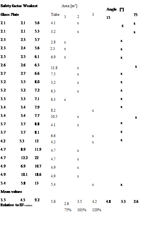
For making it easier to see any general trends about what are a good and a less good construction, a compilation of the safety factors and the varied parameters were made, which can be seen in table 4.
In the upper part of the table each row shows the safety factors of one solar collector. The x-marks describe the configuration. In the lower part of the table, the mean values for each column is presented. For the columns describing configuration, the mean values are the averages of the SFweakest of the x — marked rows. The last row shows the quotients between each column’s mean value in relation to the mean value of SFweakest.
 |
|
Two parameters show significant importance to the safety factor. The important factors are area and angle. for setting figures of the impact of the parameter a trend analysis was done. The formula of the mean safety factors dependence of the area is expressed in (6)
N. B. the matrix of input data for the areas and angles were centered in order to keep a low condition number. They were also divided with maximum deviation in order to make them easier comparable.
|
|
 |
|
 |
The purpose of this work was using commonly used dimensions and materials when building collectors. However, there are variations in almost all dimensions between different commercial collectors, and when trying to keep down the analysis data some of the factors where set constant.
The shape and design of the connection between glass and absorber has influences on the stresses in the materials, especially in the connections. In the absorber there is no maximum of stresses in the connection points. This makes the maximum stresses trustworthy also in other designs, at least when the stresses can be distributed in a less concentrating way at the connection point. In the glass the case is the opposite since the maximum of stresses is in the connection to the absorber. This makes probably the maximum of stress in the glass in this article dependant on the choice of connection. And our speculation is that the maximum stress in the glass always will be a question of how the connection is designed, i. e. the maximum of stresses in the absorber is more or less universal while it is not that for the glass.
There are numerous parameters influencing the strength of a gas filled solar collector. The most obvious parameters are the distance between glass and absorber, the area of the absorber and the angle build by arctan(width/height). The safety factor increases with low angles (long tubes), big areas and small distances.
It is not clear to the same extent about selection of material, thicknesses etc. If you take a look again at table 4 and make a comparison between the 3 and 4 mm glass respectively on the 2 m2, 45°, absorber plate in aluminium, you can see that the one with a thicker glass has a smaller safety factor. By choosing a thicker glass the safety factor of glass raise, but at the same time the safety factor for the tubes goes down and will be the weakest safety factor. Therefore, a strengthening of one part can punish itself if it is too big.
There are no special restrictions of either using Copper or Aluminum in the collector. Here we only examined 0.5 mm Aluminum and 0.25 mm Copper, due to thermal demands.
The stresses in the glass are affected by the connection to the absorber. When using other connections the calculations have to be redone.
|
Nomenclature
min Minimum |
[1] M. F. Ashby, and D. R.H. Jones, (1998), Engineering Materials 1, 2 edn, 0 7506 3081 7, Butterworth — Heinemann.
[2] B. Sundstrom, (1998), Handbok och formelsamling Hallfasthetslara (Hand book and formula collection in mechanics of materials), 2 edn, Institutionen for hallfasthetslara KTH, Sodertalje.
[3] N. Khorasani, Design Principles For Glass Used Structurally, (Lunds universitet), pp 79, ISSN 1103-4467, 2004
[4] S. Sunnersjo, (1992), FEM i praktiken (FEM in practice), 2 edn, 91-7548-541-9, Industrilitteratur AB, Uddevalla.
[5] J. A. Duffie, and W. A. Beckman, (1991), Solar engineering of thermal processes, First edn, 0-471-51056-4, John Wiley & Sons, Inc.
B. Eng. Kurt SchOle, (FH) Thorsten Siems,
(FH) Yan Schmitt
Kollektorfabrik
K. Schule & T. Siems GbR
WaidmattenstraBe 6
Germany, 79232 March-Buchheim
E-Mail: info@kollektorfabrik. de
Phone: +49 (7665) 9471521 Fax: +49 (7665) 9329796
Abstract
There are several good reasons to cover the future energy demand as much as possible with renewables. In future, energy (oil, gas, wood etc.) will become more and more expensive. More than ever, it is important to have a safe supply of the energy for cooling / heating or for industrial processes. Therefore also more solar thermal collectors will be necessary in the future. Solar thermal systems need a solar collector that guarantees an intrinsically safe operation. Solar air collectors can guarantee that. Solar thermal air systems are particularly important for solar cooling, since many countries in the world do have electricity shortages in summer. The solar thermal industry is striving to cope with the fast-growing energy demand for heating. The sector has to deal with the rules of the open market. Their solutions have to be visible, sustainable, reliable and at the end, they have to be cost efficient. Kollektorfabrik has developed a new solar air collector, which meets these requirements.
Keywords: solar air collector, solar fraction, stagnation, process heat
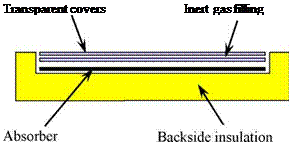
The main challenge while improving flat-plate collectors is to reduce their heat losses without sacrificing too much of the optical properties. Possible measures are:
• double glazed collectors with anti-reflective (AR) glasses
• hermetically sealed collectors with inert gas fillings
• additional glass or foil covers with low emission coating
 |
 |
The first two approaches were applied e. g. by the SCHUCO company.
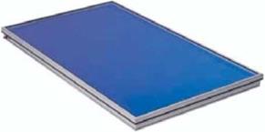
Figure 1: Construction of the SCHUCO double glazed AR flat-plate collector
(Source of left picture: SCHUCO)
The aim o f the development was to create a flat-plate collector with high efficiency at temperatures up to 120°C for process heating and solar air-conditioning purposes. Since most of the heat lost in a flat plate collector is lost via the front side, it is necessary to reduce heat losses here. This is achieved by double-glazing.
Due to anti-reflective coating the optical efficiency of 80 % is nearly equal to a single glazed standard flat-plate collector. The space between the glass panes is filled with an inert gas to reduce the heat conductivity. This collector is already available on the market.
|
Xing Li12*, Zhifeng Wang1, Bowei Wang1 1 Institute of Electrical Engineering, Chinese Academy of Sciences Beijing 100080, P. R.CHINA 2 Himin Solar Energy Group Co.,Ltd, Dezhou, Shangdong 253090, P. R.CHINA Corresponding Author, [ixing2002@126.com |
Abstract
In this paper, the thermal performance of a solar collector with evacuated tube is investigated. Main application for this collector is water heating for domestic or large building, several parameters may affect the performance of the collector, such as the water flow-rate, the different irradiance, the variable inlet water temperature, the flow configuration (series or parallel connection of tubes) etc. These parameters may all be considered in the effort to optimize the overall design. In this study efficiency curves are presented from experimental measurements. And the fit equation of efficiency is provided. After a long period test, the actual efficiency curve in different months will be compared together. Also, the test results in a certain day are presented in order to analyze the comprehensive relationship among inlet temperature, ambient temperature and solar irradiance. Besides, the results of this procedure test can be very useful, firstly, for the local solar manufacturers’ equipment in order to design and optimize its products and secondly, by the engineers in order to select and design the most suitable system.
Keywords: All-glass evacuated tube collector, thermal performance, and solar heating system
Solar energy is receiving much more attentions in building energy systems in recent years. Solar thermal utilization should be based on the integration of solar collectors into buildings. In most cases, the main utilization is provided with solar water heating system.
In 2005, most of solar energy systems manufacturing in different countries reported a good growth. In all these countries, the export sector is gaining importance. The expected expanding market for solar water heating system demands a standardized test method. In order to gain the optimistic benefits between the investment of heating system and the final results through operating the system, it is also necessary to know clear about the truly thermal performance of the collector, and further process in prediction of thermal performance in different install locations and long-term operation. Moreover, the knowledge of the thermal performance of solar collectors are essential for the prediction of the energy output of any solar thermal system, especially the overall evaluation and design for a water heating system.
Test methods for the thermal performance characterization of solar collectors are different with each other, mainly difference concluding the duration time of test period, the definition of test condition, and mean temperature of the working fluid. Most well-known test methods, such as ISO9806-1 and EN12975-2, are under steady-state conditions to test the thermal performance of the collector. These
steady-state test methods require the strict testing conditions very much in variable climates. And then the actually lasting test period should be longer than the regulated time that the climate condition is ideal to measure. However, because of the extensively regional and application of the international standards, ISO9806 is promulgated to measure the performance of collectors in in-depth study. At the same time it is clear to identify the definition of solar collectors according to ISO 9806.
There are many kinds of solar collectors, in this paper all-glass evacuated tube collector will be presented and experimented. It is a collector composed of an array of dual-glass evacuated tubes using water as the working fluid. The tubes are either all collected in parallel, or divided into two groups connected in series, within each of which the tubes are collected in parallel. Water is fed into the glass tubes through a brass tube flowing towards the closed end where it is reversed backwards then flows through the tube and is collected in the header from where it may be directed into its final use.
The all-side thermal performance of collector will be analysed to supply ample data to the design. So in order to make a comparison, at identical working conditions, between different products within a reference test condition, in this paper the experiment will be operated under steady conditions according to ISO 9806. Although the performance of solar collector can be approximately predicted based on steady test method, it is also affected by the inlet water temperature, water flow rate, and ambient conditions. Consequently, it is necessary to establish a test that can consider the whole conditions and it can be used to by engineers or manufacturers in order to design solar water heating system and optimize them.
Figure 3 illustrates the absolute frequency in hours per year of maximum absorber temperatures for collectors without and with thermotropic overheating protection (solar transmittance of thermotropic layer in clear state: 0.85; residual solar transmittance of thermotropic layer in opaque state of 0.20,
0. 30, 0.40, 0.50 or 0.60). The collector was assumed to face stagnation only. For the collector without overheating protection absorber materials are required which display a long term service temperature of 125°C associated by adequate durability when exposed to temperatures between 125 and 160°C for 400 hours per year. By the use of thermotropic layers with a residual solar transmittance of 0.20 in the opaque state the absorber material is exposed to a maximum temperature of ~90°C and to temperatures between 80 and 90°C for 1000 hours per year. If thermotropic layers with a solar transmittance of 0.40 above the switching threshold are applied, absorber materials are required that can withstand temperatures between 80 and 100°C for periods of ~1000 hours per year. For thermotropic layers with a moderate reduction of solar transmittance to values of 0.60 absorber materials are exposed to temperatures between 110 and 130°C for less than 200 hours per year and for 1000 hours between 80 and 110°C. Special polyolefin grades are available with show sufficient durability under such stagnation conditions [6]. This indicates that the development and design of thermotropic layers exhibiting a solar transmittance below 0.60 in the opaque state, would allow for the application of cost — efficient plastics as absorber materials.
|
Fig. 3. Frequency of maximum absorber temperatures per year for a collector with twin-wall sheet glazing and
black absorber (a=0.95, є=0.90), being installed in Graz (south oriented, slope 45°) and facing stagnation only;
dotted line: collector without overheating protection; other lines: collectors with thermotropic glazing (solar
transmittance of thermotropic layer: 0.85 in clear and 0.20, 0.30, 0.40, 0.50 or 0.60 in opaque state).
Within this paper theoretical modeling was applied to characterize the potential of thermotropic layers to prevent overheating of an all polymeric flat-plate collector. The investigations showed that for a collector with twin-wall sheet glazing and black absorber stagnation temperatures can be reduced by using thermotropic layers in the glazing. For thermotropic glazing the switching temperature should range between 55 and 60°C. In general, the impact of a thermotropic layer on overall collector efficiency was detected to be low as long as the solar transmittance exceeds 0.85 in the clear state. To provide an excellent limitation of the stagnation temperature to a maximum operating temperature of ~85°C a residual solar transmittance of the functional material about 0.25 was found to be effectual. If thermotropic materials are applied exhibiting an excellent reduction of solar transmittance to values of 0.20 the absorber reaches temperatures of 80°C to maximum 90°C for 1000 hours per year when installed in Graz (AUT) and facing stagnation only. Even with functional materials that show moderate switching ranges to a solar transmittance of 0.60 in opaque state stagnation temperatures between 110 and 130°C as well as between 80 and 110°C are reached for ~200 and ~1000 hours per year, respectively. Thus, the development and design of thermotropic layers with a residual transmittance below 0.60 in opaque state would allow for the application of cost-efficient plastics as absorber materials.
[1] A. Khan, A. Brunger (1997). In Proceedings of the 23rd Annual Conference of the Solar Energy Society of Canada Inc, Vancouver, Canada, pp. 119-124.
[2] G. M. Wallner, K. Resch, R. Hausner, Solar Energy Materials and Solar Cells, 92 (2008) 614-620.
[3] P. Nitz, H. Hartwig, Solar Energy, 79 (2005) 573-582.
[4] SOLAR, 1997-2006, “Warme — und stromungstechnische Berechnungen, Unterprogramm: Theoretischer Kollektor“, AEE INTEC, Gleisdorf, AUT.
[5] M. Meir, J. Rekstad, (2003). In Proceedings of 1st Leobner Symposium Polymeric Solar Materials, Leoben, Austria, pp II-1-II-8.
[6] S. Kahlen, G. M. Wallner, M. Meir, J. Rekstad, (2006). In Proceedings of EuroSun 2006, Glasgow, UK, pp. 7ff.
The research work of this paper was performed at the Polymer Competence Center Leoben GmbH within the framework of the Non Kpius Program.
This work is funded by the State Government of Styria, Department Zukunftsfonds Steiermark.
A. Haberle, C. Zahler, F. Luginsland, M. Berger
PSE AG, Emmy-Noether Str. 2, 79110 Freiburg, Germany
ah@pse. de, +49.761.47914-14
Abstract
Industrial process heat in the temperature range of up to 250°C is a huge but almost untouched field for solar thermal technologies. State of the art non tracking collectors have their limits at a maximum operation temperature of 150°C. Higher temperatures can be reached with concentrating collectors, which are mostly developed for solar thermal power generation with an operation temperature higher than 300°C and a field size of at least several MWp.
Only a handful of companies and institutes target the enormous potential for solar industrial process heat, which can be defined by an operation temperature range of 100°C up to 250°C and a power range of around 50 kWth up to a few MWth (peak capacity). Plenty of applications for this power and temperature range can be found e. g. in the food and textile industries but presently the most attractive option is solar thermally driven air conditioning. PSE AG developed a linear concentrating Fresnel collector, that uses individually tracked reflector rows to concentrate direct solar radiation to a stationary linear receiver. The Fresnel approach offers a relatively simple and low cost construction with low wind loads and high ground coverage, which makes this technology well suited to be installed on flat roofs.
In December 2005 a first prototype of the PSE linear Fresnel process heat collector was installed in Freiburg, Germany. The collector was operated and evaluated in co-operation with the Fraunhofer Institute for Solar Energy Systems. A second prototype with 132 m2 (66 kWp, th) aperture area was installed in Bergamo, Italy to power a H2O/NH3 absorption chiller. The complete solar cooling system is operated and monitored since August 2006 to evaluate the system performance as well as the performance of the individual components. The third installation with 352 m2 (176 kWp, th) was installed in late 2007 to power a double effect LiBr/H2O chiller at the University of Seville, Spain. The latest installation is a solar cooling system with a H2O/NH3 chiller at a winery in Tunisia.
In this paper we present our experience with the construction and give design values and measurement results of the collector prototype and demonstration systems.
Keywords: linear Fresnel, concentrating collector, process heat, solar cooling
The prototype collector has an aperture area of only 2 m2 with a width of 1 m and a length of 2 m. Consequently it is lightweight and can be easily used for roof installation. The rotation axis is equal to the absorber tube axis, so that the absorber stays in a fixed position during process while the parabolic body rotates around the absorber tube. Therefore there is no need of expensive flexible pipe connections. The collector consists of a stainless steel body, an evacuated absorber tube, a high-reflective aluminium mirror from the German manufacturer ALANOD (4200 GP Miro-Silver 2) and an anti-reflective solar glass cover from the German manufacturer FLABEG. For actuation and tracking the sun, a step motor drive with worm gear and a sensor is applied.
The aspired operating temperature level is 120 to 200 °C. The power is about 1 kW per module and the collector has an efficiency of around 63 % at solar direct radiation of 800 W/m2 and a temperature of 160 °C. Measured at the collector test facility at the SIJ, the illustrated efficiency curve of Fig. 1 with an optical efficiency of q0 = 0,7 and a linear and quadratic heat loss coefficient of a1 = 0,204 W/(m2K) and a2 = 0,0015 W/(m2K4) was determined:
|
Fig. 1. Efficiency of the prototype collector PTC 1000 |