Как выбрать гостиницу для кошек
14 декабря, 2021
The solar storage tanks display their storage capacity not until the collector temperatures are higher than the desired consumption temperature. The higher the „over-temperature“ in the tank is the higher the storage capacity.
Assumed the heating temperature is adjusted at 60 °C and the back flow has 50 °C. A high temperature collector with low volume flow feeds a buffer tank (start temperature 60 °C) to 90 °C in one step. For every litre at 90 °C 4 litres of water at 60 °C can be fed into the heating network. A low temperature collector needs 3 times the tank volume to yield the same heat energy at 70 °C. If the heat from the buffer tank is used through a heat exchanger, the usable water quantity will be
much smaller and the cooler buffer of less value because the cooler the storage tank is the more usable heat (exergy) is lost by heat exchange.
C. Estrada1*, D. Riveros-Rosas1, J. Herrera-Vazquez2, Sergio Vazquez-Montiel2, Camilo A. Arancibia-Bulnes1, C. Perez-Rabago1, F. Granados-Agustfn.
1 Centro de Investigation en Energia, Universidad Nacional Autonoma de Mexico. Av. Xochicalco s/n;
Temixco, 62580 Morelos, Mexico.
2 Institute Nacional de Astrofisica, Optica y Electronica. Luis Enrique Erro 1, Tonantzintla, A. P. 216, 72000
Puebla, Mexico.
* Corresponding author, cestrada@cie. unam. mx
Abstract
In the present work, the optical design for a new high radiative flux solar furnace is described. Several optical configurations for the concentrator of the system have been considered. Ray tracing simulations were carried out in order to determine the shape and intensities of the concentrated radiative flux distributions in the focal zone of the system, for comparing the different proposals. The best configuration was chosen in terms of maximum peak concentration, but also in terms of economical and other practical considerations. It consists of an arrangement of 409 first surface spherical facets with hexagonal shape, placed on a spherical supporting structure. The facets have corrected orientations in order to compensate for aberrations. The design considers an intercepted power of 30 kWt and a target peak concentration above 10,000 Suns. For the design, global optical errors from 0 to 6 mrad have been considered, but it is found that the maximum tolerable overall error will be of 4 mrad.
Modern solar furnace technology starts in the 1950s decade. The first research in these devices was directed towards studying the effects of high temperatures (around 3500°C) on the properties of different materials exposed to highly concentrated solar fluxes [1]. Among their applications is the study of properties like thermal conductivity, expansion coefficients, emissivity, melting points [2], study of ultra refractory materials, and determination of phase diagrams, crystal growth, and purification of materials. At the same time, methods for the measurement of high temperatures in receivers [3], and the flux density of concentrated radiation [4] have been developed. The latter have evolved and image digitalization techniques are used [5], with calorimetric techniques as reference for the images [6].
Among the first built, there were the furnace of Arizona State College in the USA, in 1956 [7], and the furnace of the Government Institute for Industrial Research, in Japan. Solar furnace technology has evolved, and larger furnaces with higher concentration factors have been built, like the one of the CNRS in Odeillo, France, with 1000 kW [8]; the furnace of the Academy of Sciences of Usbekistan, with 1000 kW [9]; the furnace of Paul Scherrer Institute (PSI), of 25-40 kW [10]; the furnace of CIEMAT, in Plataforma Solar de Almeria, Spain, with 45 kW; and the furnace of DLR, in Cologne, Germany, of 20 kW [11].
Mexico has an ideal position for the implementation of solar technologies, due to its favorable geographical location in the Sunbelt of the planet. The estimation is a yearly average of more than 5.5 kWh per square meter of global solar radiation over the country. In particular, in the northwest states this insolation has a very important component of beam solar radiation. This high quality
solar resource makes that area ideal for the implementation of concentrating solar technologies (CST), either for electrical power generation or for the production of solar fuels as Hydrogen. For these reasons, the construction of a high radiative flux solar furnace (HRFSF) was proposed, as a research tool to allow the development of CST in Mexico. Federal funding for the development of this infrastructure has been approved by CONACYT, and the project is now in progress. The HRFSF will be developed in three years, starting from September 2007, by the Centro de Investigacion en Energia of Universidad Nacional Autonoma de Mexico (CIE-UNAM), in collaboration with Instituto Nacional de Astrofisica, Optica y Electronica (INAOE), and other institutions. The applications of this infrastructure are expected to be in the areas of solar chemistry and solar materials processing [12].
The design targets for the HRFSFS are a thermal power of 30 kW, peak concentration above 10000 suns, and a solar spot of 10 cm diameter or smaller. To achieve these targets, the design was carried out by means of ray tracing simulations, to optimize the optical characteristics of the system.
We started from an initial proposal of a faceted concentrator of around 30 kW, formed by polished first surface glass mirrors with spherical curvature. From the results reported in [13] about the influence of the number of facets in the concentration factors, we sought that the concentrator had the largest feasible number of facets. The size of 40 cm was selected, on the basis of fabrication and mounting considerations. The shape of the facets was chosen to be hexagonal, because this geometry fills adequately the concentrator surface, still being relatively easy to polish. From the point of view of filling the space, square facets would be an interesting option also, but they are difficult to polish adequately.
Also, from the results of [13], it was decided to mount the mirrors on a curved frame, either spherical or parabolic, instead of a flat structure (like from instance in the DLR [11] or in NREL), which would be the easiest option. This has the advantage of reducing the average distance of the facets to the focal point, and therefore reducing the spread of the reflected solar cones.
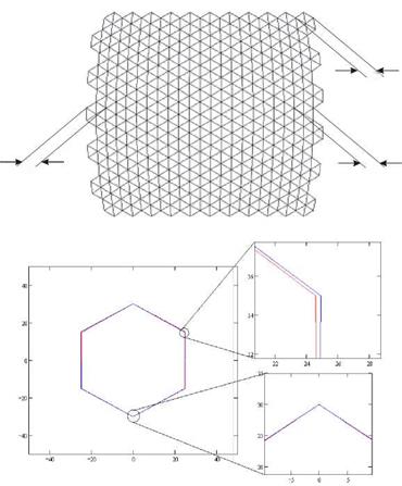
In Fig. 1, the hexagonal mirrors mounted on a circular frame are projected onto a flat surface. The shape of each mirror must be designed according to this projection to minimize mutual shading.
For this, the vertical dimensions of the mirrors were not altered, changing only the horizontal dimensions in order to fit the mirrors on the arrangement. The difference with respect to regular hexagons is actually small, but it must be taken into account in the fabrication of the facets.
In the present optical system the spherical aberration of the facets is important. Due to this aberration and, in a smaller degree, to comma and astigmatism, the focal region is increased in size (Fig. 2). Facets that are on the most external parts of the concentrator contribute more to these aberration effects, because they are facing the incoming radiation with more inclination.
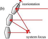
Aberrations can not be corrected with additional optical surfaces in a system like this. A lot of improvement can be made however, by reorienting the facets to different inclinations. The angle for each facet is chosen such that the ray reflected on the center of the facet is effectively directed towards the focal point of the system, as illustrated in Fig. 3. In this way, even though the facets are mounted on a spherical frame, they are not tangent to the surface of the frame.
|
|
|
|
|
|
|
Figure 2. Effects of the spherical aberration.
In addition to the reorientation of the facets, using different focal distances for each one may also help to compensate for the aberrations. Several cases were simulated, which are compared against a continuous paraboloid of equivalent area and focal distance:
• E1: Sphere with reoriented facets. All facets with the same focal distance.
• E2: Sphere with reoriented facets. All facets with a different focal distance, calculated according to their distances to the actual focus.
• E3: Sphere with reoriented facets. Facets in six different groups of equal focal distance.
• P1: Paraboloid with reoriented facets. Similar to case E2, but with paraboloidal frame.
• P2: Paraboloid with reoriented facets. Focal distances in groups, as case E3.
• P3: Continuous paraboloid.
 |
 |
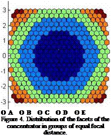
In configurations E3 and P2, only six different focal distances are used, on the assumption that the optical performance could be reasonably good, as compared to the case in which every facet has its own focal distance. This possibility is explored because restricting the number of different focal distances would be very advantageous to reduce fabrication costs. The groups of facets are shown in Fig. 4, and their data reported in Table 1.
Figure 3. Reorientation of facets (b) for correction of the spherical aberration (a).
The modeling of the above configurations was carried out under the assumption of perfect specular reflection; i. e., reflectivity equal to unity and zero optical errors. Based on the results obtained, one of these configurations was selected for further investigation. This configuration was then simulated with different values of the optical error, in order to determine the maximum tolerable value of this parameter for the construction of the system.
 >
>
Each simulation run was carried out with two ray trace codes of different nature, to ensure the reproducibility of the results. The first one called Tonalli [13, is a code based on the convolution method [14], and developed in collaboration between CIE-UNAM (Mexico) and CIEMAT, Spain. The second was a routine for reprocessing the results from a commercial optical design software, called Zemax.
|
Table 1. Groups of focal distances considered for cases E3 and P3
|
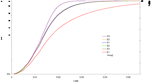
T he results for the different configurations are presented in Table 1 and Fig. 6. The best result is, as expected, for the control case of a continuous paraboloid (P3). On the other hand, the four configurations E2, E3, P1, and P2, are very similar to each other; there is practically no difference in peak concentration between the paraboloidal and spherical frames, either when all facets have different focal distances (E2 and P1), or when they are grouped in six focal distances (E3 and P2). The case with a single focal distance (E1) is the worst of all, indicating that it is at lest necessary to consider a few different values for the focal distance. Five or six turned out to be a good number in preliminary analyses.
|
Table 2. Results of the simulations for the proposed configurations.
|
Once it was determined that a spherical frame is a good option, the next step consisted in studying the effect of the curvature radius of this frame. It was considered that a smaller radius could improve the concentration by reducing the distance the reflected solar cones travel, and therefore limiting the spread of the solar image. In Fig. 6 the variation of peak concentration with curvature radius is presented. It is observed that the best concentration is obtained for curvature radius between 500 and 550 cm. However, the concentration factor for the studied cases has a maximum variation of only 1.3%. on the other hand, the rim angle of the concentrator increases considerably as the radius of curvature is reduced. A large rim angle may result inconvenient for the implementation of receivers in the focal zone, due to the large incidence angles of radiation, as illustrated in Fig. 7. So there is little to gain from the reduction of the radius and there are potential problems with this. Therefore a radius of 7.5 m was fixed for the following simulations, giving a effective focal distance of 3.68 m.
 |
The next study was to analyze the effects of optical errors in the performance of the concentrator. For this purpose, the E3 configuration was considered. Reflectivity was taken as 0.81 and focal distances according to the previously described groups. In Fig. 8 the results are presented for peak concentration, average concentration and spot radius (for 90% collected power). We can see that with values of the optical error between 3 and 4 mrad, the peak concentration is between 15000 and 10500 suns, while spot radius would be between 4 and 5 cm. So, a maximum optical error of 4mrad is required to meet the design targets stated above for the solar furnace.
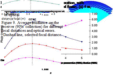
It is known that optical errors modify not only the concentration factor but also other characteristics of a faceted concentrator, like the optimal focal distance [13]. In Fig. 9 we present
 |
 |
the average irradiance values for different focal distances and optical errors. In this case we consider a configuration of the type E2.
As can be seen from Fig. 8, even tough there is a dependence of the optimal focal distance with optical error, the variation is not sharp. The previously selected focal distance of 3.68 m is well within the optimal range for the errors considered.
It must be pointed out, that the optical error we are considering here is the global error of the system. This includes the alignment and surface errors of the facets, but also the alignment, surface, curvature, and tracking errors of the heliostat. Therefore, the upper bound of 4 mrad must accommodate for all of these effects. Actually, the type of facets considered can be fabricated with very high accuracy, and also an accurate alignment procedure is being developed for the facets of the concentrator. Therefore, the design of the heliostat may prove to be the more critical problem.
A specific heliostat design is in process, where the target would be to minimize all optical errors.
The design of the HRFSF aims to create a high quality infrastructure for research in solar concentration systems in Mexico. The design considers a faceted concentrator, formed by 409 hexagonal first surface polished glass mirrors. The mirrors will be attached to a frame of spherical curvature. Ray tracing results indicate that there is very little difference in optical performance between a parabolic and a spherical frame, but the latter may be easier to fabricate. It was found that it is not convenient to use mirrors of equal focal distances, mounted tangent to the frame curvature. Instead, mirror should have different focal distances and must be tilted with respect to the frame. This helps compensating for the optical aberrations. It was found that grouping the mirrors in 6 sets of equal focal distances gives very good results. Also, the effect of optical errors was investigated. It was found that error must be below 4 mrad to reach the design targets.
This work was partially supported by CONACYT (Grant 56918) and UNAM (Grant 372311721).
D. Riveros-Rosas and J. Herrera-Vazquez acknowledge graduate scholarships from CONACYT.
[1] Glaser, P. E. Solar Energy, 2 (1958) 7-10.
[2] Hisada, T., Mii, H., Noguchi, C., Noguchi, T., Hukuo, N., and Mizuno, M., Solar Energy, 1 (1957) 14-18.
[3] Brenden, B. B. et al. Solar Energy, 2 (1958)13-17.
[4] Loh, Eugene et al., Solar Energy, 1 (1957) 23-26.
[5] Jonhnston, G., Journal of Solar Energy Engineering, 117 (1995) 290-293.
[6] Perez-Rabago, C. A., Marcos, M. J., Romero, M., Estrada, C. A., Solar Energy 80 (2006) 1434-1442.
[7] Kevane, C. J., Solar Energy, 1 (1957) 99-101.
[8] Trombe, F., Le Phat Vinh, A., Solar Energy, 15 (1973) 57-61.
[9] Abdurakhamanov A. A. et al. Applied Solar Energy, 34 (1998).
[10] Schubnell, M., M., Kelle, J., Imhof, A, Journal of Solar Energy Engineering, 113 (1991) 112-116.
[11] Neumann, A., Groer, U., Solar Energy, 58 (1996) 181-190.
[12] Fletcher, E. A., Journal of Solar Energy Engineering, 123 (2001) 63-74.
[13] Riveros-Rosas, D., Sanchez-Gonzalez, M., Arancibia-Bulnes, C., Estrada, C., EUROSUN Congress, Lisbon, Portugal. October 7-10, 2008.
[14] Biggs, F., Vittitoe, C. N.. “Helios model for the optical behavior of reflecting solar concentrators”. Sandia National Laboratories Report, SAND 76-0347, Albuquerque, USA (1979).
[1] Introduction
Solar desalination, an environment-friendly technique, is successfully used for the production of fresh water from saline seawater in many parts of the world. In the last decade, with the rise of fuel cost, an extensive research has been carried out by different institutions worldwide to develop an efficient way of utilizing solar energy for water desalination.
The heat pump is a useful device in transforming low-grade thermal energy into a usable energy source. Heat pumps can use many sources, such as ground [1], to provide useful energy for
To compare the solar fractions that are reached with and without a conventional storage tank, the ranges of solar fractions from both nomograms are shown in a single diagram in Figure 7.
 |
Because of the limited storage capacities of the concrete slab, significantly larger collector areas are necessary to reach the same high solar fractions as with a conventional storage tank. Therefore, the cost-to-benefit optimum for systems using the concrete slab as a heat store has been limited to a solar fraction of 30%. Please note that this is only an approximate value and depends strongly on the boundary conditions of each project.
Solar thermal energy is a good solution for space heating of industrial buildings if there is no or not enough waste heat available. When considering solar thermal energy for space heating of a factory building, the first steps should be to reduce the heat demand of the building by insulating the building and reducing infiltration losses (e. g. loading docks instead of open doors). The nomograms were developed to provide a means for rough dimensioning typical system configurations. A system concept with a water storage tank and a system concept using the concrete floor slab as storage medium were analyzed and described in detail. If the utilization ratio is high, the solar fractions that can be reached are similar for both system concepts. Solar fractions reached with systems without storage tank can even be higher compared to systems with storage tanks. High utilization ratio means that either one or both the collector area or the heat requirement is low. In these cases, the cheaper system concept without a storage tank makes a lot of sense. However, if the heat requirement is relatively large or if very high solar fractions should be reached, the system concept with a storage tank has an advantage. It should be noted that the option of having no storage tank and reaching a 100% solar fraction is feasible if an air temperature in the building that sometimes falls below the desired set value can be tolerated.
The presented work was performed as part of IEA-Solar Heating and Cooling and Solar Paces Task 33/IV “Solar heat for industrial processes”. The Austrian participation was financed by the Austrian Federal Ministry of Transport, Innovation and Technology.
[1] Klein, S. A. et al. (2005). TRNSYS, A Transient System Simulation Program — University of Wisconsin — Madison, Solar Energy Laboratory, Version 16.
A preliminary assessment of the dimensioning of both solar field and storage system is based in the simulation results obtained for a system without backup energy. This assessment is based in two parameters: the capacity factor, CF (the ratio of annual values of mechanical energy produced by the solar cycle and the maximum mechanical energy that could be produced by the cycle operating continuously at full load), and the global solar to shaft power conversion efficiency, □ SORC, (the ratio of annual values of mechanical energy produced by the solar cycle and solar energy incident on the solar field) calculated with equations 2 and 3, respectively.
![]() VT, annual
VT, annual
Wyj, x 24(^ / day) x 365(days / year)
![]()
 |
VT, annual
Г SORC ~
KQcol, annual
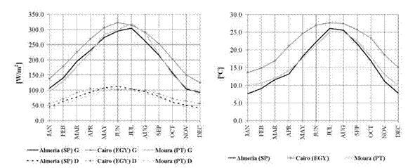
The results obtained for both cycles at the three tested locations are presented in figure 3.
These results allow a parametric analysis of solar field area and storage time dimensioning, revealing the effect of storage time increase over solar to shaft power conversion efficiency results. For cycle 2, these results are more limited than those obtained for cycle 3, which reveal a wider range of storage capacity volumes leading to increased system efficiency.
The results presented in table 4 allow a comparison of the dimensioning of the system, at the three tested locations, after a reference condition of (CF = 0.3, maximum r/SORC).
Fig.3 — Capacity factor (CF) and solar to shaft power conversion efficiency (nSORC) results obtained for yearly
simulations of cycle 2 and 3 at Almeria (SP), Cairo (EGY) and Moura (PT)
|
Table 4. Solar field and storage capacity dimensioning for reference conditions of capacity factor CF = 0.3 and maximum global solar to shaft power conversion efficiency, rjSORC for cycles 2 and 3 at tested locations
|
The wort boiling is the key process within a brewery. Because of the high thermal energy consumption and the high temperature level, two heat recovery systems that can cover the hot water demand of the whole brewhouse or even the whole brewery are usually installed.
Within the last 100 years, there has been a continuous development of the wort boiling process by the brewing industry. The main objective was to reduce the amount of water that has to be evaporated, which results in shorter boiling time and reduced energy demand. So it was possible to reduce the amount of evaporated water from more than 16% (equals a boiling time of more than 120 min) to 3..5% (35..50 min), while increasing the quality of the produced wort. At present, there are lots of boiling systems available that are offered by different companies. These systems differ mainly in the used boiling copper, its position within the brewhouse, the process control (continuous or batch), heat exchangers, pressure and temperature profiles as well as used heat recovery installations [9].
The wort boiling at the Hutt brewery takes place by so called classical internal boilers at atmospheric pressure. In the beginning, the wort is heated from 74°C to boiling temperature by indirect heating of the outer surface of the wort copper. After reaching the boiling temperature, the wort flows several times through an internal boiler that is placed directly in the copper. While passing the tube bundles of this boiler, the wort is heated under pressure to about 101..105°C.
While leaving these tubes, the wort starts to evaporate. Compared to the state of the art within wort boiling, this boiling system is relatively simple and old. It consumes a high amount of thermal energy, due to the required time and temperature for atmospheric boiling, the relatively high amount of water that has to be evaporated and the missing insulation of the boiling copper [10].
To clarify the operating mode of heat recovery installations within a brewery, figure 2 displays the initial state of the wort production at the Hutt brewery in a simplified way. Two hot water storage tanks, each 50 m3, are installed to cover the hot water demand of the whole production process, including filtration and bottle filling hall. These tanks are connected in serial and charged by two heat recovery installations. The first storage tank is fed by the heat exchanger within the process step of wort cooling and has a temperature level of maximally 80°C. The second store is fed by a tube bundle heat exchanger that condenses the vapours which occur during wort boiling. Two modes of operation can be chosen: heating cold brewing water to 80°C, or increasing the temperature of the already stored hot water. All consumers of the brewery are fed by the second storage tank with the higher temperature level. The main hot water load is caused by mashing (58°C) and lautering (78°C). Other consumers with lower hot water consumption are cleaning processes, sterilisation and keg filling. If process steps require lower temperatures than the storage tank temperature, the stored water is mixed with cold water. The consumed amount of water from store number two is settled by the first storage tank. An additional heating device that runs with steam ensures a set temperature of minimum 80°C in the upper part of storage tank number two during weekends or longer periods with no heat recovery.
|
Fig. 2. Initial state in the brewhouse at Hutt brewery. |
As mentioned before, there are multitude wort boiling systems available. These systems differ in the way of heating lauter wort and the used boiler. The overall objectives for this process step are to assure a gentle and rapid heating of lauter wort and gentle wort boiling with low shear forces. Further on, large evaporator surfaces, good circulation and mixing of wort and a limited but sufficient boiling time is requested [11]. Based on these and even more requirements, every brewhouse manufacturer has its own solution for the ideal wort boiling system. These can be classical internal or external boilers, thin-film evaporators, dynamic low-pressure boiling, high — temperature wort boiling, secondary evaporation under vacuum or downstream thin-film evaporation [10]. All of these systems vary a lot in the overall energy consumption, due to the boiling process as well as the heat recovery installations, which influences the water balance of the whole brewery.
Based on the relatively old and inefficient atmospheric wort boiling at the Hutt brewery, the technical management planned to implement one of these new boiling systems. During the planning phase, two different boiling systems were under consideration: a vacuum boiling system and dynamic low-pressure boiling. The vacuum boiling is characterised by a special geometry of installations and two boiling phases (atmospheric and vacuum) that are adjustable at will and cause a reduced evaporation. The whole boiling procedure takes place in a cycle consisting of a storage vessel, an external boiler (calandria) and an expansion evaporator in which a vacuum can be applied depending on the respective boiling mode. A tube bundle heat exchanger will be used to condense the vapours and pre-heat cold water. The main advantage of this boiling technology is the reduced effort for implement all installations in the existing brewing process. Besides savings of thermal energy, this boiling system shows an increased electricity demand for generation of
vacuum. The dynamic low-pressure boiling represents boiling at slight positive pressure with periodically increased and subsequently reduced pressure. An internal boiler is mostly used for heating and boiling. This boiling system is combined with a special heat recovery system that uses the condensation enthalpy of vapours to pre-heat the lauter wort. This heat recovery system consists of a common tube bundle condenser, special high temperature storage and an additional heat exchanger for the lauter wort [12].
To establish solar kilns as an industrial tool, performance tests must be carried out during different season periods, based on objective data taken from measurement and analysis of several parameters. In this work, the inclusion of permanent measurement and control instrumentation has been adopted, which is an innovative aspect introduced for SECMAD project.
The main objective of the measurements and analysis is to characterize solar kiln performance, regarding operation time and costs under several weather conditions, as well as the related evolution of relevant physical quantities like: inside the kiln chamber, air circulating temperature and relative humidity and moisture contents (MC) of drying wood; at the solar collector zone, air temperature and relative humidity; air temperature and relative humidity on the outside environment;
Wood equilibrium moisture contents (EMC) in the interior and exterior of the kiln are also calculated from these measurements; as they are usual and useful drying indicators in the lumber sector that integrate the contribution of both temperature and relative humidity conditions. Additionally, energy expenditure, solar radiation and air convection can also be measured. Optimization of operational conditions to reduce drying time was considered and can be carried out automatically by the control instrumentation, where a dedicated fuzzy algorithm takes into account the restrictions imposed by quality issues and acts upon the ventilation system, presenting a flexible response to the natural change of exterior conditions (solar radiation, and psychometric conditions of external air, etc.).
Measurements and control can be taken at operator’s defined constant intervals that can lie in the range for one minute to several hours, with a usual value of 15 minutes. Instrumentation system also offers data logging and monitoring capabilities.
A major problem with solar kilns is related with the uncontrollability of environment conditions and the difficulty to repeat them in consecutive drying operations. Therefore, all results are dependent on the specific weather conditions, besides of kiln structure, drying product and control strategy.
However, for similar weather conditions (solar radiation and relative humidity), some common evolution patterns have been noticed. Figures 3 and 4 represent one entire week evolution of temperatures and equilibrium moisture contents in the exterior and in the interior of a solar kiln charged, respectively, with moisture saturated wood and medium dried wood (MC ~ 30%). In both situations, there was sunny weather and the ventilation was switched on during the day period.
Data on these figures were acquired, respectively, during autumn and winter 2006 at INETI Lisbon facility — 38° 46’ N, 9°10’ W.
The efficiency of the kiln, illustrated by EMC values, is lower in the early hours of the morning, but increases with radiation intensity. As can be seen, EMC values present always less amplitude variation inside than outside the solar kiln. Although EMC values at the interior are higher during winter than in autumn, as expected, drying conditions can be quite favourable inside of the kiln during the winter period.
In spite of ventilation, chamber peak air temperatures (around midday) showed to be in the worst case 3-5°C higher than the outside ones. These small increments in temperature are sufficient to low relative humidity and EMC, in a significant way, causing these quantities to attain their lowest levels at this time and promoting wood moisture loss, in a more effective way. In fact, wood moisture loss increases with the decrease of relative humidity, mainly due to the increase of the water vapour pressure differential, which is the key factor for moisture evaporation. In this way, wood works as an additional moisture source inside the kiln, increasing RH and EMC. This effect is more intense if the wood is saturated as in the case of figure 3, where the chamber EMC values are bigger than the exterior ones (in opposite of figure 4, where wood has already attained 30% of moisture content), in spite of the ventilation.
If, in this case, exchange with the exterior is prevented, internal RH and EMC values would attain much bigger values. In such situations air has to be continuously expelled to the exterior and renovated at a high rate, forcing air circulation through the wood-stack.
|
—— Exterior EMC |
Interior EMC |
|
—— Interior Temperature |
—— Exterior Temperature |
Fig. 4 — Wood temperature and moisture equilibrium content inside and outside of the kiln,
December (winter), one wee
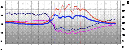
Figure 5 shows another typical evolution pattern of the equilibrium moisture content and temperature during a summer sunny day, both inside and outside the solar kiln, charged with saturated pine wood. Vertical lines correspond to the beginning and end of ventilation period, during which the ventilators were switched on and off.
 |
|
It can be noticed, that even though the ventilation is on, during the hours of bigger incidence of solar rays, chamber temperature suffers a bigger increase than in autumn or winter, causing a bigger drop in the interior EMC values and offering better drying conditions
Fig. 5 — Typical summer day equilibrium moisture content and temperature
Evolution inside and outside the solar kiln
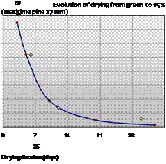 |
Global results of an entire drying operation, during the end of autumn and the beginning of winter, using 27 mm thickness boards of pine wood, in a total wood volume of 40 m3, are illustrated in figure 6. Expelled moisture rate was increased by proper exposition of the wood boards to the air. The 40m3 volume of 27 mm thickness boards presented a total surface exposition (two faces for one board) of 3000 m2.
Fig. 6 — Drying process evolution of water loss (left) and moisture content (right).
In the first drying phase, high air circulation was provided, in order to speed as much as possible the drying rate. It should be emphasized that another important reason to quickly reduce wood moisture content at the initial stage, is to prevent the development of mould or blue stain specially when drying softwoods, namely pine. In the illustrated example, at the beginning of the process, an extraction of 75 liters of water per cubic meter was achieved (Figure 6). This represents a total water removal from wood in 24 hours about 3000 liters. This water removal rate dropped in seven days to about 35 liters per cubic meter and a value of 12 % in moisture content was reached in 33 days.
Figure 6 shows some other details of the final stage of the drying operation. Although temperature has not exceeded 30°C the wood moister content (MC) was reduced from 30 % to 15 % in only 7 days. This is quite significant, taking into account that the final drying stage is the slowest in a solar kiln. As can be seen, the EMC during this phase reached an average value of 9 % along the day when temperature increases and relative humidity was at its lowest (RH).
Monitoring data acquired during several runs under variable conditions, in all prototypes, allow the proposal of expected durations for the drying of softwood according to the different weather conditions. Table 1 summarizes the expected drying duration for different board thicknesses and favorable or less favorable conditions, based on the tests carried out during the project.
|
Table 1 — Expected solar kiln drying duration for softwood (Pinus pinaster, Aitim.), from 120% to 14% M. C.
|
Regarding energy, it must be said that the total amount needed to dry wood is the same whatever the method. For pine wood, the heat energy needed is about 494 kWh / m3. In conventional kilns, this energy is usually obtained from burning residues that can be quite cheap, but it must be remembered that the investment on a boiler is very high and the combustion produces CO2 emissions. In air or solar drying, the use of solar energy greatly reduces the expense and gas emissions. In the case of the present study, the kiln has a low cost structure and only energy spent in electrical ventilation has a cost per operation.
|
Table 2- Compared energy use in a solar kiln and a conventional kiln drier for softwood (Pinus pinaster, Aitim.), from 120% to 14% M. C. .
|
3 Conclusions
The present work showed that low cost solar kilns can be competitively used to dry wood, presenting balanced benefits regarding operation time vs. final quality, energy expenditure and gas emissions.
A performance evaluation based on relevant physical quantities measurements and analysis is being carried on, during different season periods and weather conditions, constituting an essential tool to gather knowledge about the process. The results, documenting kiln functionality, strongly contribute to adjust the control to specific needs of products to be dried and to establish confidence in this kind of drying methods for industrial use.
As referred, in the first stage, wood drying requires a great capacity of water extraction, so strong ventilation should be carried, being necessary to extract the moisturized air from the kiln trough entire air renovations (1 to 3 per minute). In these circumstances, during sunny hours the gain in air temperature inside the kiln can be as small as 2 to 5 degrees. Although this apparently low increase
in temperature, the equilibrium moisture content can drop about 5 to 8 %, which is enough to dry wood at a very satisfying rate, even at its final stage.
Electric power reduction can be achieved through ventilation control, according to external conditions and drying level already obtained. It was found out that even forced air convection is always of great benefice, exchange with the exterior can be restricted, most of the time, to day hours (8h per day approximately).
A well designed structure and ventilation control strategy are the key factors for the economic success and drying quality. Even though drying times and energy expenditure have been acceptably low, more improvements can be eventually achieved.
One example is the possibility of allowing internal air recirculation in some circumstances, without exchange with external environment. This will account with another important ventilation effect, that wasn’t addressed in the present work, which is the removal of water vapor accumulated around the wood as a thin skin, whose presence diminishes the vapor pressure differential and favors the occurrence of mould blue stains that can affect final appearance and quality.
Combination of solar drying with conventional layout drying processes, including an adequate active control for optimization purposes, is another open possibility to achieve competitive substitution of fossil sources of energy, with significant decreasing of CO2 emissions, while still requiring low cost investments. Modifications of the industrial process are claimed to be minimal since the system requires no specialised buildings or electrical power, but should be clarified in furtherer works.
Acknowledgments — The information provided in this paper is a result of an applied research and demonstration project, partially financed by EU founds, and included in PRIME program, under the financial management of Innovation Portuguese Agency and managed by INETI.
[1] Ronald Voskens, Frank Zegers. 2005. Solar Drying in Europe. ECOFYS. IEA task 29.
[2] Maria J. Martins, Antonio Nogueira, Edgar Ataide, Sandra Enoch, David Loureiro, Arnaldo Cruz Costa, Alvaro Ramalho, Jose Santos, Luis Pestana. 2005. Monitoring and Control of an Energetically Efficient Wood Drying Process. EFITA Conference. UTAD. Vila Real.
[3] Titta, M.; Olkkonen, H., 2002. Electrical Impedance Spectroscopy Device for Measurement of Moisture Gradients I Woods”, Review of Scientific Instruments, Volume 73, N.8, August 2002, pp. 3093-3100.
[4] Steinmann, D. E., 1995. Real Time Simulation of Solar Kiln Drying of Timber. Solar Energy, Vol. 54,
N.5, pp.309-315
[5] Joly Patrice, More-Chevalier Francois, 1980. Theorie, pratique & economie du sechage des bois. Edition H. Vial., Durban
[6] Nogueira, A.., 2003. Estudo de estrategias de controlo para secador solar. XI Congresso Iberico e VI Iberoamericano de Energia Solar.
[7] Nogueira, A.., Ataide, E.., Martins, M. J.., Enoch, S., Loureiro, D.., Costa, A. C.., Santos, A.., 2005. Simulation and control strategies for an energetically efficient wood drying process. EFITTA /W CCA 2005 Joint Conference, Vila Real, Portugal, 25-28 July.
[8] Maria J. Martins, Antonio Nogueira, Edgar Ataide, Sandra Enoch, David Loureiro, Arnaldo Cruz Costa, Alvaro Ramalho, Jose Santos, Luis Pestana. 2005. Secador de Madeira Energeticamente Eficiente. Relatorio tecnico cientifico do projecto. INETI. Lisboa.
[9] Santos, J. A.; Martins, Maria J.; Costa, Arnaldo C.; Loureiro, D.; et al, investigadores Del INETI. 2006. Creada una camara de secado de costes bajos que reduce en dos terceras partes los consumos energeticos de un secador convencional. Comercio e Industria de la Madera (CIM) Editorial RBI, C/ Entenza 28 Entlo. 08015 Barcelona.
[10] M. N. Haque, et al. 2005. Assessment of the Actual Performance of an Industrial Solar Kiln for Drying Timber. Drying Technology, 23: 1541-1553. Copyright Q 2005 Taylor & Francis, Inc.
The channel burner model assumes a complete combustion. It evaluates the fuel consumption, the output mass flow and the composition of the exhaust gas by a given mass flow of air entering the
burner and a desired temperature. This burner model is used in the gas turbine as well. The gas turbine consists of a compressor, a burner, a turbine and a generator. Compressor and turbine are computing the resulting enthalpy and power consumption or production by using an inner efficiency. In addition, a pressure ratio can be set by the user.
Solar Cycle
The heliostat field model is based upon a simple field efficiency table interpolation dependent of the site, date and time. Only the total power to the receiver is calculated. The receiver outlet mass flow and temperature are calculated from the mass and energy balance and are dependent of the inlet conditions of the air flow and the concentrated radiation input.
Gas and steam properties can be integrated to each model. The different state variables are computed for Water and Steam by polynoms taken from the industry standard IAPWS-IF97 and for different gas mixtures by algorithms given in the VDI Guideline 4670 and provided by NASA.
Each model component created has the following advantages:
• is compatible to all others
• enables calculation for different site locations
• is applicable for different power plant sizes
• can be adjusted to different transport media: e. g. gas, exhaust gas
• easy modification
• can be used for short time scales down to minutes
Every planner and user is interested in an efficient all-season application of the solar collector system. The performance of low temperature collectors drops considerably with falling outside temperatures. In winter or with not optimal weather they can never achieve much more than a preheating.
If heat is needed at different levels at the same time, e. g. for heating and hot water supply, the simplest solution is to provide and storage it at the highest level i. e. with the highest thermodynamic value. This is impossible with low temperature collectors, what leads to higher planning efforts and much more complicated hydraulic systems.
The missing of the predicted energy harvest with most of the large-scale projects with low temperature collectors was always explained by higher return-flow temperatures than planned. In fact, the return-flow temperatures are never the problem but the collectors itself because they lose substantial performance under real working conditions.
The system consists of two main parts, a solar assisted heat pump, with refrigerant as its working fluid, and a water desalination section with preheats, as shown in Figure 1.
The solar assisted heat pump provides heating and cooling to the desalination process, with a serpentine tube solar evaporator collector that absorbs solar radiation and ambient energy. Refrigerant R134a is used as the heat pump’s working fluid. The serpentine tube, with 9.52 mm diameter was soldered at the back of the absorber plate. The bottom of the collector was insulated with polyurethane material. An open type reciprocating compressor, directly coupled to a three phase induction motor was used in the system. A frequency inverter controls the speed of the motor. Refrigerant passes through condenser coil, located at the bottom of the desalination chamber. To ensure complete condensation of the refrigerant, it is allowed to pass through a 250 l
[4] LEP: (Liquid Entry Pressure) if the feed pressure is higher than the LEP, then the liquid penetrates the membrane pores and the hydrophobicity is lost [8]. The LEP depends on many factors, but the main one is the membrane pore size, logically the bigger the pore size is, the smaller the LEP is and so is the working pressure.
[5] In the case of C3, the optimal cycle parameters correspond to evaporation at critical conditions.
Considering the stability of ORC operation, the maximum allowed evaporation temperature was bounded, in this analysis, to a value of 145 °C, 9 °C bellow the fluid critical temperature.
R. Battisti1*, S. Drigo2 and C. Vannoni2
1 Ambiente Italia, Via Vicenza, 5/a 00185 Roma, Italy
2 University of Rome “SAPIENZA”, Department of Mechanical and Aeronautical Engineering,
Via Eudossiana, 18 00184 Roma, Italy
* Corresponding Author, riccardo. battisti@ambienteitalia. it
Abstract
The majority of the solar thermal plants operating today provide hot water to households, for both sanitary purposes and space heating. Although the residential sector offers a huge potential for solar thermal applications, the industrial sector should not be ignored for two key reasons.
First, this sector shows a remarkable relevance, covering about 28% of the total primary energy consumption for final uses in EU25.
Second, a significant share of the heat consumed in the industrial sector is in the low and medium temperature range. About 30% of the total industrial heat demand is required at temperatures below 100 °C and 57% at temperatures below 400 °C. The areas of application with the most suitable industrial processes include cleaning, drying, evaporation and distillation, blanching, pasteurisation, sterilisation, cooking, degreasing and surface treatment.
These two issues make the industrial sector a promising and suitable application for solar thermal energy.
In the paper, both the results of the analysis of the existing solar thermal plants for process heat and the assessment of the application potential will be described. Both activities have been carried out in the framework of IEA SHC and SolarPaces Task 33/IV.
Keywords: Solar Thermal, Industrial, Potential, Process Heat
Considering the new applications for solar thermal, the industrial process heat at low and medium temperature up to 250 °C is one of the most promising. Industrial sectors such as food, wine and beverage, textile, transport equipment (e. g. car washing), surface treatment (e. g. galvanic) and the chemical require process heat in this temperature range. The areas of application are numerous and include different processes such as cleaning, drying, evaporation and distillation, blanching, pasteurisation, sterilisation, cooking, degreasing and surface treatment. In addition, several built examples showed that space heating of factory buildings has to be considered one of the most promising applications of solar thermal in industry.
A survey on the existing solar thermal plants for industrial process heat (SHIP, Solar Thermal for Industrial Applications) and a review of the potential studies for future applications have been
performed in the framework of the IEA Solar Heating and Cooling Programme and SolarPaces Task 33/IV: the results are summarised in the present paper.
At the end of 2006, the installed solar thermal capacity worldwide [1] was about 118 GWth (168 million m2). Compared with 144 GWel for wind and 5,5 GWel for photovoltaic, solar thermal is helding a leading position among renewables. The majority of the solar thermal plants operating today provide hot water to households. Although the residential sector offers a huge potential for solar thermal applications, the industrial sector should not be ignored for two key reasons.
First, this sector shows a remarkable relevance, covering about 28% of the total primary energy consumption for final uses in EU25 [2]. Second, a significant share of the heat consumed in the industrial sector is in the low and medium temperature range. These two issues make the industrial sector a promising and suitable application for solar thermal energy.