Как выбрать гостиницу для кошек
14 декабря, 2021
Сегодня каждый, кто собирается в отпуск и не знает, с кем оставить своего котика или кошку, может во[...]
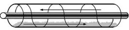
In an extruder reactor (see Fig. 6a), the extruder transports the material and additionally causes stirring, thereby improving vapour and heat transport. The effectiveness of the transport depends on the rotational speed of the screw. The heat can be added or removed by means of either a jacket around the screw tube, or a hollow screw. This would be a convenient way of integrating the means of transport required for the powder and the reactor. If there is risk of the TCM material sticking to the screw, a system with two parallel self-wiping screws may be applied.
|
0 0.02 0.04 0.06 0.08 0.1 0.12 rotational speed (1/s) |
 700 600 500
*
 400 300 200 100 0
Fig. 6. (a) TCM extruder reactor, (b) extruder heat transfer (Jephson model, in (Kalbasenka, 2008))
For the case of dehydration of the TCM, assuming that the heat transport would be the limiting factor for the power, for a 3kW reactor and an effective heat transfer to the wall of about 550 W/m2K, this would lead to a reactor of about 1 m in length and 5 cm diameter, in which about 75% of the open volume would be filled with TCM.
Paul Gantenbein,
Institut fuer Solarenergie SPF,
HSR University of Applied Sciences of Rapperswil, Oberseestrasse 10, CH-8640
Corresponding author, paul. gantenbein@solarenergy. ch
Abstract
The power of a closed solid sorbent — gas/liquid sorbate system is limited by the material combination sorbent — sorbate, the external heat sources, the geometrical structure of the fixed sorbent bed and the heat transfer in both the fixed bed to a fixed bed immersed heat exchanger and in the liquid sorbate tank. In the adsorption process the speed uT of the temperature front moving through the fixed bed of spherical zeolite particles is depending of the position z in the fixed bed and is reduced for increasing length z. In a fixed bed of spherical zeolite particles the speed uT is higher and the length of the water vapour mass transfer zone is longer for zeolite particles with a larger diameter dp. After a process cycle time t=200s to t=300s the maximum power — i. e. cooling power in the sorbate tank is reached. For longer cycle times a linear decrease of the cooling power was measured. While in a closed heat storage water vapour flows through the fixed bed of spherical zeolite particles the pressure drop Ap/p and thus the thermal power Pth has a linear dependence of the length z of the fixed bed. This power decrease is directly correlated with a decreasing water vapour pressure gradient. A closed solid — gas/liquid sorption system is more suitable for a heat pump or a cooling machine application than for thermal storage.
Keywords: Solar energy, adsorption heat storage, fixed bed, packed bed, trickle bed, vapour pressure drop, heat pump
1. Introduction
In conventional low temperature solar systems the solar irradiation is converted into heat and stored in hot water tanks. The correlation between thermal losses and the temperature level of the storage device are physically implied. Thus, a loss free heat storage able to release its energy immediately is a desirable characteristic. An exothermic reaction in a chamber with a minimum of two chemical components stored apart from each other would fulfil these two requirements while adsorption of water vapour on sorbent materials like zeolite or Silicagel in a closed system satisfies principally the first requirement. For the desorption of the water from the zeolite solar thermal energy can be used. Beside of solar energy as the high temperature level source the structure of a system will depend on the sorbent — sorbate materials and their undergoing phase transitions as well as on the geometrical structure of the sorbent.
The subject of solid sorbent — vapour sorbate closed heat storage systems has recently gain specific attention because of reports of high energy densities of such a sorption module [1, 2, 3]. But in a laboratory scale system using up to 1.5kg modified zeolite sorbent [4] and in a real sized system with 2×1.1m3 of silicagel sorbent [2] after a strong increase of the output temperature an eminent decrease of this temperature could be observed. So, the output power of the sorption module is strongly depending of the operation time and thus of the dynamic behaviour in the coupled mass and heat transfer.
The measurements of water vapour adsorption on zeolite and silicagel as a function of time and water vapour pressure in a closed system showed a time range of t=300s to t=400s of high mass adsorption [5]. Saha and Boelman [6, 7, 8] were reporting about operational conditions and coefficient of performance COP of an adsorption refrigeration machine working with the sorbent silicagel and the sorbate water. The optimum cooling power output was found to be in a cycle (adsorption / desorption) time of t=250 s to t=300s while the COP of the machine increases up to a cycle time of t=1800s.
Therefore, further work was undertaken for a better understanding of the sorption module fixed bed and to find answers to the questions of what limits the size and structure of a closed heat storage module. In this work the first steps to the design for the power and energy output of a closed low temperature solid sorbent — vapour/liquid sorbate sorption heat storage system depending on the thermodynamic and the geometric parameters are presented. In the following the term fixed bed is used as an equivalent term of packed or trickle bed.
2. Experimental
To measure the dynamic behaviour in the adsorption of water vapour on spherical zeolite 13X particles in a closed system an vacuum tight stainless steel equipment was set up. In Fig. 1 a schematic of the water tank and the fixed bed containing tank is shown. The two tanks are connected through an on/off manually driven ball valve containing pipe of d=40mm diameter. A top view photo a) and the schematic b) arrangement of the pressure and temperature sensors are shown in Fig. 2. With the 10 radially inserted 8mm diameter tubes the pressure in the centre of the fixed bed tube is measured with a capacitive acting sensor. These sensor tubes are in a spiral arrangement with l=50mm equally spaced over the whole length L=500mm of the fixed bed tube and act also as the canal for the four wires of the Pt100 temperature sensors. For a good heat transfer a Zeolith particle was glued on the ceramic oblique cube of the Pt100 sensor. The fixed bed tube has a diameter D=160mm and the particles are fixed at both ends with two stainless steel fabric of s=0.8mm mesh size. The spiral arrangement of the sensor tubes are meant to a perturbation free water vapour flow can be expected.
|
1) |
|
L |
|
2) |
|
Fixed bed |
|
■10 T(z) P(z) |
|
l: |
|
nz |
|
Sensor 1 d |
|
to 10 |
|
p(T) |
|
T(HX in) |
|
Water tank |
|
-^T(HX out) |
|
Fig. 1: Schematic of the experimental setup with the fixed bed of spherical zeolite 13X particles container 1) and the water sorbate tank 2). |
|
1) Sorbent fixed bed (D, L, dp) 2) Water / sorbate tank (p, T) |
|
Diameter D a) Photo 2 1 |
|
b) Schematic |
 |
 |
>
Fig. 2: Top view photo a) of the (empty) fixed bed tube of diameter D with the radial inserted tubes to measure the pressure. These tubes act also as temperature sensor cable canal.
The measurements were carried out with two different zeolite 13X fixed beds of average spherical particle diameter of dp=1.51mm and of dp=2.63mm, respectively [9]. This leads to the aspect ratios of approximately D/dp=106 and D/dp=61, and to a bed length to particle diameter ratio of L/dp=3 31 and L/dp=190, respectively. The temperature level i. e. the pressure level in the water sorbate tank was set to T(HX in)=15°C, T(HX in)=20°C and T(HX in)=25°C. The corresponding pressures at the entrance to the fixed bed are listed in table 1 [10]. The hydraulic diameter dh in table 1 is determined with the equation (1) [11],
d = (1 — s’) f (1)
|
sdp |
|
1 |
in equation (1) s is the porosity of the fixed bed and the shape factor f=1 of spherical particles. The porosity s is determined through the equation (2) [12],
dp
s = 0.375 + 0.34*-^- (2)
|
Temperature T(HX in) [°C] Pressure p (sorbate tank) [mbar] |
15 16.3 |
20 23.4 |
25 29.7 |
|||
|
Particle diameter dp [mm] |
1.51 |
2.63 |
1.51 |
2.63 |
1.51 |
2.63 |
|
Porosity s [-] |
0.41 |
0.43 |
0.41 |
0.43 |
0.41 |
0.43 |
|
hydraulic diameter dh [mm] |
0.168 |
0.292 |
0.168 |
0.292 |
0.168 |
0.292 |
|
Table 1. Temperature T and pressure p in the sorbate tank — particle and hydraulic diameter in the fixed bed. |
The bulk density of zeolite 13X is 650 kg/m3 and the BET surface is in the range of 500m2/g and 800m2/g [9]. zeolite 13X has an average pore size of 1nm. In humid air the water uptake c(p, T) of the this sorbent material is approximately 25 wt.%. The sorbent material fixed bed was dried at room temperature by pumping with a Leybold turbo-molecular pump in series with a Pfeiffer mechanical vacuum pump. The water tank was evacuated to the temperature dependent water vapour pressure
[10] . For pumping out the air dissolved in the deionised water in the lower tank, the procedure was performed three times. The data acquisition was done with an Agilent data acquisition switch unit.
3. Results and Discussion
M. Hadjieva1*, M. Bozukov1, Ts. Tsacheva2
1 Central Laboratory of Solar Energy & New Energy Sources, Bulgarian Academy of Sciences,
72 Tzarigradsko Schosse blvd., 1784 Sofia, Bulgaria
2 Institute of Physical Chemistry, Bulgarian Academy of Sciences, G. Bonchev, bl. 11, 1113 Sofia, Bulgaria
* Corresponding Author, sthermal@phys. bas. bg
The modified phase change materials (PCM) are the promising new source for cost effective heat storage systems integrated in industrial process solar/heat technology. Application of the modified PCM storage units to heating/cooling technology allows a multiple utilization of solar/thermal energy by repeatable heat cycling process. After years of development and use of typical PCM with diverse heat returns in practice, the modified PCM, which succeeded over some PCM drawbacks or/and add a new function, are a practical choice for heat storage and recovery of solar/thermal energy. Novel modification of the inorganic salt eutectics absorbed within a graphite matrix to produce a highly thermally conductive multifunctional composite was designed for thermal storage at a high temperature cooling technology (up to 250oC). The (Na/K)NO3 eutectics/graphite composite improved thermal conductivity of typical PCM like inorganic salts, (Na/K)NO3 eutectics, which temperature range of phase transition and heat storage capacity are appropriate for solar/thermal storage at the industrial solar steam process. Detailed analysis and control of the specific structuring of salt/graphite composites for long-term thermal stability and function at high temperature heat storage technology of solar concentration electrical plants were in the special focus of this study. Results showed elemental separation and forming the Na-rich spherical masses and the K-rich layered structure over the graphite plane as the effect of the eutectics solidification mechanism that influence strongly thermal storage behaviour of the (Na/K)NO3 eutectics/graphite composite.
Keywords: Phase change material, (Na/K)NO3 eutectics, PCM/graphite composite, latent heat storage technology
The modification of phase change materials responds to new ideas of solar/thermal industrial technologies to ensure complete energy utilization through heat storage process. Integration of thermal storage system in novel technologies is an ultimate need for well-organized economical functioning and saving heat/energy. Knowledge, collected on typical PCM and thermal storage applications with a varied income in a past century, lets to meet requests of new thermal technology demands. Progress in advanced PCM modification for improving typical PCM behaviour or use additional PCM functions for technology perspectives need a multidisciplinary innovative work to produce efficient storage materials according next generation PCM requirements. The successful paraffin modifications with graphite were developed for achievement of a quality new property (thermal conductivity) and advantage of the PCM heat
storage systems for an industrial process technology. [1,2]. The PCM composites, based on (Na/K)NO3 eutectics and graphite, were elaborated in the framework of EU project DISTOR [3].
S. Warerkar[10]*, S. Schmitz1, J. Gottsche1, B. Hoffschmidt1, R. Tamme[11]
1 Fachhochschule Aachen, Solar-Institut Julich, Heinrich-Muflmann-Str. 5, 52428 Julich, Germany
2 DLR, Institute of Technical Thermodynamics, Pfaffenwaldring 38-40, 70569 Stuttgart
* Corresponding Author, warerkar@sij. fh-aachen. de
Abstract
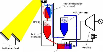
In view of rising energy prices and an increasing share of power generated by renewable energy sources, the importance of energy storage is growing. In the framework of this project a thermal energy storage concept for solar power towers is being developed, in which quartz sand serves as storage medium. Sand is suited due to its properties of high thermal stability, specific heat capacity and low-cost availability. Compared to storages based on ceramic bodies the usage of sand promises to reduce costs of energy storage and thus to reduce the costs of electricity generation. Beside solar thermal power plants the storage concept could be applicable in steel industry.
A central element of the storage concept is an air-sand heat exchanger, which is presently under development. This paper describes simulation results and measurements of the heat exchanger prototype. It includes sand flow behaviour and experience with different porous walls as well as up-scaling options.
Keywords: energy storage, thermal storage, heat exchanger, sand
|
volumetric receiver
fluid bed cooler Fig. 1 Sand storage concept for solar power towers |
The sand which is heated up in the air-sand heat exchanger to approx. 800 °C flows to the hot storage through a down pipe and further to the fluid bed cooler. The fluid bed cooler, a unit which is a standard component of fluidized bed combustion units, is the driving element of the steam cycle. The generated steam is finally fed to the steam turbine for power generation. The cooled sand exits from the fluid bed cooler at a temperature of approximately 150 °C and returns to either the air-sand heat exchanger or is stored in the cold storage tank.
The main advantages of the storage concept are:
• Low-cost storage medium
• Storage at ambient pressure
• Almost 100 % of the hot storage volume can be used
• The heat exchanger pressure losses are independent of the storage capacity
For implementation of the concept a suitable heat exchanger is required, which was developed and analysed at SIJ and is described in the following.
A. Rysanek1* and S. J. Harrison1
1 Solar Calorimetry Lab, Department of Mechanical and Materials Engineering, Queen’s University,
Kingston, Ontario, Canada K7L 3N6
|
* |
![]() Corresponding Author, rysanek@me. queensu. ca
Corresponding Author, rysanek@me. queensu. ca
Abstract
A prior study has validated the Short-Term Thermal Stores (STTSs) in use at the Drake Landing Solar Community in Okotoks, Alberta, Canada against various CFD modelling schemes. In this work, a set of alternative designs to the STTSs is developed in CAD, and further evaluated using CFD. The alternatives designs incorporate the use of large baffles to direct flow and encourage stratification. The designs are simulated under three charging modes: constant inlet temperature and flow rate, constant inlet temperature and variable flow rate, and variable inlet temperature and flow rate based on an energy profile. A proposed characterization index, deemed in this paper as the Exergy Charge Ratio (^Cr), has been mathematically derived and also applied to this work. Initial results indicate that the tj^Cr may improve the assessment of mixing within a thermal energy store at the early stages of charging. The research may be of significant interest for future applications requiring large thermal energy stores, such as solar district heating networks, or industrial heating processes. Keywords: Thermal storage, exergy (available energy), solar district heating, CFD
1.1. Background
Prior studies have highlighted the applicability of Computational Fluid Dynamics (CFD) to model the transient behaviour of thermal energy stores [1][2].Among the benefits of flow visualization, the finite volume discretization inherent to CFD allows for the effective analysis of a thermal energy store (TES) using the Second Law of Thermodynamics, whereby quantifiable variables, such as the internal entropy within a TES, can be more easily assessed than in a laboratory setting. This study will provide another practical application of CFD as a design tool for thermal energy stores, using the Drake Landing Solar Community in Okotoks, Alberta, Canada, as a case example.
With the configuration of components shown in Figure 1 at least five operational modes are possible. The cooling requirement of the rooms is met either by the absorption chiller or by the ice store. On the other hand it is also possible to use the ice store to support the absorption chiller, if higher cooling requirements are necessary to cool the rooms than the absorption chiller is able to deliver.
If no air conditioning is necessary the ice store is charged by the absorption chiller, for example on weekends. If the absorption chiller produces more cooling energy than required by the rooms it is possible to discharge and charge the ice store simultaneously. In this case the rooms will be cooled by the ice store and the ice store will be charged by the absorption chiller.
Ring Sopark is a new housing area outside Bradstrup with app. 500 single family houses. The first part (100 houses) will be supplied with district heating, but in a way that makes it CO2 — neutral. Altogether the houses will have app. 1.000 m2 roof, integrated solar collectors (50-100 m2/roof), 2.000 m2 ground mounted solar collectors, 1.000 m3 accumulation tank and a compressor heat pump to cool the ground mounted solar collectors. Surplus heat in the summer period will be “lent” to the district heating system covering the rest of the city and “barrowed” again in the winter period. One of the topics of the project is to show that collective solutions for bringing down CO2 — emissions from houses are cheaper than individual solutions in the house.
The project will demonstrate
• Roof integrated solar collectors delivering to the district heating network.
• CO2 — neutral houses to lowest costs for the society.
• Extended regulation possibilities for electricity.
• Optimises district heating network with a heat loss of 15-20% in new areas with single houses.
• Central control of heat demand from the district heating system to each house making it possible to lower the forward temperature in periods.
The project is supported from the Danish state to make it feasible compared to the present heat production price from the district heating plant, but when the energy frame for buildings will be lower, the costs can be fully paid by the consumers because the investment costs for reduction of fuel consumption are lower than the investment cost in the single house for the same reduction.
The first part is expected to be build in 2009.
Major developments of the projects are two pre-industrial prototypes hereafter referred as OPICS1 and OPICS2, see Figure 1. Main features of these prototypes are:
• Prototype OPICS1 : ICS with a TIM-cover, a water store of 75 l and with a modular rectangular shape (of about 1m x 0.75 m x 0.20 m) that facilitates its integration in buildings. Other technical parameters are:
• Maximum relative pressure acceptable in the tank is limited to 1 atm
• Use of a high selective coating in the absorbing surface
• The absorbing area is of 0.75 m2
• The daily solar efficiency after 24 hours of outdoors exposure without draw-off is in the range of 55 %.
• Prototype OPICS2: ICS with a TIM-cover, a PCM store with an internal heat exchanger that permits to transfer energy from the PCM to the thermal fluid, and with a modular rectangular shape (of about 1m x 0.75 m x 0.15 m) that permits the integration in buildings. Other technical parameters are:
• Maximum relative pressure acceptable in the thermal fluid is above 10 atm
• Use of a high selective coating in the absorbing surface
• The absorbing area is of 0.75 m2
• The daily solar efficiency after 24 hours of outdoors exposure without draw-off is in the range of 50 %.
Both pre-industrial prototypes have been modelled, constructed and tested in detail following ISO procedures [4,5]. The tests included measurement of the daily efficiency, measurement of the heat loss coefficient and measurement of the draw off process. The tests have also been modelled using simulation tools [2,3], and good agreement has been observed between the experimental and numerical results. This has proved the credibility of the numerical model.
The numerical model has also been used to estimate the yearly performance of the new prototypes when installed in different climates and for four different demands corresponding to four reference applications:
• Pool heating
• Domestic hot water
• Space heating
• Absorption cooling using a LiBr-H2O machine of simple effect.
Three climates have been considered which corresponded to the cities of
• Barcelona
• Almeria (South of Spain)
• Copenhagen.
In order to analyse the advantages of the new prototypes, simulations of the OPICS prototypes have been compared to simulations of two ICSs using standard materials (no TIM nor PCM) and with a water store equal to the water store of the prototype OPICS1. They are referred as refl and ref2. The reference ICS refl uses a black paint as selective coating (low-medium selective coating), while the ICS ref2 uses the same high selective coating that is used in the prototypes OPICS1 and OPICS2.
Results have shown that, as already known by the solar thermal community, it is very important to use high selective coatings, because the industrial cost can be similar to that of low or medium selective coatings and energy gains are drastically increased.
Results from the yearly performance estimation also show as in all climates and applications, the energy gains in the solar systems are higher when using the OPICS prototypes than when using the standard ICS with a high selective coating, ref2. For applications at low temperature levels as pool heating and domestic hot water, the increase in the energy gains is small, in the range from 0 to 5 %. The explanation is that the use of TIM mainly contributes to a reduction of the heat losses through the cover due to convection effects, and for low temperature levels, thermal losses through the cover are low. For applications at higher temperature level, space heating and absorption cooling with the LiBr-H2O machine of simple effect, as thermal losses through the cover are more important, the reduction of the convection effects leads to a drastic increase of the energy gains. For the space heating application, this increase is in the range from 35 to 50 %. In the absorption cooling application, the reference prototype ref2 is only able to have energy gains in very hot and insulated climates as in Almeria. In other colder climates, even in the Mediterranean climate of Barcelona, no energy gains can be obtained from the ICS ref2. On the other hand, the OPICS prototypes are able to have energy gains in all climates.
In the project OPICS Integrated Collector Storage (ICS) devices have been developed using Transparent Insulation Materials (TIM) and Phase Change Material (PCM). Main features of the prototypes are a compact design that facilitates their integration in facades and roofs of buildings and an improved efficiency with respect to the standard ICSs.
The research approach has been based on the combination of virtual prototyping techniques (numerical simulation) and the construction and measurement of experimental set-ups and prototypes following ISO procedures.
Pre-industrial prototypes of the OPICS-ICSs have been constructed, tested and modelled in detail.
Results have proved that improved efficiencies can be achieved with respect to standard ICSs, and
that they can be used in applications were standard ICSs are not able to give a reasonable
performance.
This work was funded in part by the European Commission under the Fifth Framework
Programme, Thematic Programme: Energy, Environment and Sustainable Development FP5-
EESD, Project CRAFT-1999-70604.
[1] J. Cadafalch, A Detailed Numerical Model for Flat Plate Solar Thermal Devices, Sol. Energy (2008).
[2] J. Cadafalch, R. Consul and A. Oliva, Detailed Model for the Virtual Prototyping of Flat Plate Solar Thermal Devices, Proceedings EUROSUN 2006, Glasgow.
[3] J. Cadafalch et al., Optimised Integrated Collector Storage: Low-Cost Solar Thermal Systems for Houses and Offices (OPICS). CRAFT Publishable Report, EU Contract CRAFT-1999-72476, 2005.
[4] ISO9459-2. Solar heating -Domestic water heating systems — Part 2: Outdoor test methods for system performance characterization and yearly performance prediction of solar-only systems, 1995. International Organization for Standarization, ISO 9459-2:1995(E), Switzerland.
[5] ISO9459-5. Solar heating -Domestic water heating systems — Part 5: System performance characterization by means of whole-system tests and computer simulation, 1996. International Organization for Standarization, Draft International Standard ISO/DIS 9459-5, Switzerland.
The volume of the seasonal storage tank necessary for a maximum solar fraction is calculated from the energy density of magnesium sulphate (2.52 kWh. m-3) and the part of annual heat demand which is not provided by the solar energy in the reference case. But Fig. 1 shows that a large amount of heat collected in summer by the vacuum tubes is wasted. The seasonal TESS thus enables to complete or replace the thermal energy production of the auxiliary electric heater during the winter. The solar fraction is defined here as the part of the annual heat demand covered by the solar thermal energy. The storage volumes of material are presented in the Table 1.
|
Location |
Solar fraction without seasonal storage |
Achieved solar fraction with seasonal storage |
Volume of MgSO4 (m3) |
Ratio volume of MgSO4 / Living space (L/m2) |
Mass of MgSO4 (tons) |
Mass of water (tons) |
|
Paris |
48.5 % |
50.0 % |
0.2 |
1.0 |
0.5 |
0.5 |
|
(zone H1) |
57.3 % |
0.9 |
4.8 |
2.4 |
2.5 |
|
|
Marseille |
83.2 % |
90.0 % |
0.3 |
1.6 |
0.8 |
0.9 |
|
(zone H3) |
100 % |
0.7 |
3.6 |
1.8 |
1.9 |
|
Table 1. Estimation of storage volumes |
Storage volumes ranging from 0.2 to 0.9 m3 are expected, depending on the type of climate and the achieved solar fraction. The excess solar energy available during the summer, used for the regeneration of the material, limit the storage capacity ; the solar fraction is therefore limited to a value of 57.3 % in Paris, whereas 100 % solar fraction is achievable in the sunnier region of Marseille. The summer regeneration of the material will be studied in detail in future works. It will lead to the re-sizing of the solar collectors area.
The corresponding stoechiometric amounts of water vapour, which reacts with MgSO4 during the phase of heat production, vary from 0.5 to 2.5 tons. The reactor is an open system and the water is taken from the ambient spoilt air exiting the house, which could be completed by external humid air or by an extra external air humidifier if natural humid air is not sufficient. The model is being optimised in order to get more accurate and meaningful values of the solar collector area, the volume of the tank and the control parameters with respect to the climate and the targeted solar fraction.
Two parameters are important when designing a TESS : the quantity of heat that can be stored per given volume and mass (the energy density) and the rate at which this energy can be delivered (the power density). A very high energy density is of no use if the heat is released very slowly, resulting in very low temperature lifts and unworkable thermal energy. Despite a high theoretical energy density, the practical use of pure magnesium sulphate is quite difficult. Under real operating conditions, the theoretical energy density of the magnesium sulphate cannot be reached at usable power densities. The material needs to be dispersed to react at a suitable rate, which decreases the energy density. For instance, the storage volume increases up to 2 m3 if 50 % of the theoretical energy density of the dense salt is achieved. One of the purposes of the experiments is to find a proper porous matrix to disperse the magnesium sulphate in order to reach the maximum energy density of the salt.
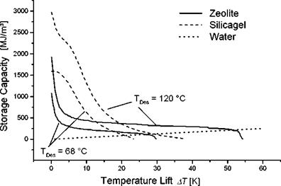
The achievable storage capacity of a sorption TES is depending on the available charging temperature and the required discharging temperature of the actual application. This relation can be calculated on the basis of the sorption equilibrium of the sorbent material. Figure 8 shows how the storage capacity depends on the temperature lift for different charging temperatures (TDes) in an open adsorption TES system [7 Dr AH]. The diagram shows curves for Zeolite and Silicagel. In addition to that the curve for the storage capacity of a hot water TES can be seen in figure 8.
It is obvious that higher charging temperatures are leading to higher storage capacities.
|
Figure 8: Storage capacity depending on the temperature lift |
In a real application e. g. the heating system requires a minimum temperature. Below a certain temperature lift the thermal energy can not be used anymore. The values for the achievable storage capacity are strongly depending on the temperature lift. They are falling drastically, when higher Temperature lifts are needed. The curves of Zeolite and Silicagel intersect at a temperature lift of about 20 K. If a lower lift is sufficient Silicagel can reach higher values, if higher lifts are required Zeolite is delivers higher capacities.