Как выбрать гостиницу для кошек
14 декабря, 2021
Сегодня каждый, кто собирается в отпуск и не знает, с кем оставить своего котика или кошку, может во[...]
Eventually, a sequence of consecutive cloudy days in winter will require discharging the TES without additional heat supply from the BIPV/T roof. A backup system is therefore necessary. One of the most important design revisions has been the change of the backup system from a large pellet boiler to a ground source loop using the same HPs as the BIPV/T system. The pellet boiler presented several shortcomings: cost, higher operating temperatures (implying more complex piping), and the need for a stock of wood pellets. In contrast, using a ground source for the heat pumps has the advantage of simplicity: a single 3-way valve allows for easy selection between the BIPV/T air and the ground to provide thermal energy to the HPs.
2.2. Solar collector and domestic hot water (DHW) system
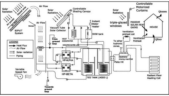
Two 20-tube vacuum (Apricus 20) tube solar collectors will be the main source of thermal energy for the DHW needs. A heat exchanger wrapped around the grey water drain (“power-pipe”) contributes to increasing the temperature of the water entering the DHW tank. The evacuated tubes will be located on the south facade of the house overhangs, at a 45° inclination angle. A heat dissipater will release excess thermal energy gathered by the collector during the summer. A controllable rolling canopy will extend over the collector and over the edge of the overhangs to improve shading during the summer months. The DHW tank will have a volume of 400 L. An internal coil, having a piping system with a set of controllable valves will allow heat transfer between the tank, the solar collectors and the TES reservoir. A desuperheater coil installed in one of the heat pumps can also transfer heat to the DHW tank via a coaxial pipe linked to the tank’s drain valve. To guarantee the supply of hot water, an instant electric water heater can raise the
|
Figure 3. Main components of the ANZEH mechanical system. temperature of the water supplied to the piping system. |
S. Tundee, N. Srihajong* P. Sakulchangsatjatai, and P. Terdtoon
Department of Mechanical Engineering, Faculty of Engineering,
Chiang Mai University, Thailand 50200.
Tel. +66-53-944151 Fax. +66-53-226014, Email: suratundee2000@yahoo. com
Department of Mechanical Engineering, Faculty of Engineering, Rajamangala University of
Technology Isan Khon Kaen Campus, Thailand.
Abstract
Solar pond is one type of solar collector with the ability to store thermal energy for long period of time and lower cost of construction compared with the other type of solar collector. An alternative method of heat extraction from solar ponds. This paper presents the thermal analysis of heat extraction process from solar pond by using the heat pipe. The numerical analysis was done by small pond has an area of 7.0 m[1] [2] and a depth of 1.5 m. The heat pipe is made of copper tube which has 21 mm. inside diameter and 22 mm. outside diameter. The lengths of evaporator and condenser section are 800 mm and 200 mm. respectively. The working fluid used in the experiment was R-134a. which located at the North-Eastern Thailand from where Khon Kaen is the site selected for this study (16° 27′ N 102° E). The simulation was done by using the energy equation and solar radiation data at the above location. The solution of energy equation for solar pond can be obtained by the numerical method. The heat transfer capacity of the sized thermosyphon will be accordingly determined. The thermal efficiency of solar pond — thermosyphon system was defined by the ratio of the amount of heat extraction by thermosyphon by solar energy input in solar pond. The frame work of estimation of heat extraction from solar pond by using thermosyphon was revealed in this research. The performance of heat exchanger is investigated by varying the air velocity which receives the removed heat at condenser section. Air velocity was found to have a significant influence on the effectiveness of heat exchangers. The effectiveness decreased with increasing air velocity. The calculated results from this theoretical model have good agreement to those from the experimental data.
temperatures increasing up to 700C at a depth of 1.32 m at the end of the summer. The minimal temperature were 260C during early spring. Of which compare ambient temperature with higher than the others. The idea of solar energy collection was conduct by creating artificial solar pond hinted by Kalecsinsky.
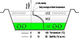 |
A solar pond generally consists of three regions, the upper convective zone (UCZ), the non — convective zone (NCZ), and the lower convective zone (LCZ), Akbarzadeh et. al.[1]as shown in Figure.1
Fig. l.The salt gradient solar pond configuration (Akbarzadeh)
1. The upper convective zone (UCZ) is the topmost layer of the solar pond. It is a relatively thin layer which consists almost wholly of fresh water.
2. The non — convective zone is just below the upper convective zone and has an increasing concentration relative to the upper convective zone, and it also acts as insulation on the lower convective zone.
|
Fig.2. Experimental apparatus |
 JCZ
JCZ
NCZ
LCZ
3.
|
Concrete |
The lower convective zone is the layer in which the salt concentration is the greatest, and there is no concentration gradient in it. If the concentration gradient of the NCZ is great enough, no convective motion will occur in this region, and the energy absorbed in the bottom of the pond will be stored in the LCZ.
When solar radiation was incident upon the solar pond, a part of the ray is reflected on the surface and most of the incident ray transmits through the working fluid. Also, apart of the transmitted ray is more absorbed by each thin layer of NCZ and LCZ and, the part of transmitted ray, which reached the LCZ, is changed into the heat and stored in the LCZ.
 |
There are many research studies on solar pond. Hillel Rubin et. al.[3]. establish the mathematical model to predict solar pond performance by using the energy equation. Later, Kurt et. al. [2] model the temperature profile in solar pond. They present the concentrate distribution behavior of solution in solar pond by means of mass transfer equation.
Two above research perfectly concluded the concept of solar pond heat capacity estimation. In side of, solar pond application, Jaefazadeh (Article in press) study the solar pond heat extraction by using the heat exchanger with water as working fluid. In this research, there are two heat exchangers. The first is installed in LCZ, the second receive heat from the first and transfer heat to the air. The fresh water is used as working fluid between both of heat exchangers.
Andrew et. al. [5] increase the solar pond performance by increasing heat transfer surface. Their works were done by installation of additional heat exchanger in NCZ and remain heat exchanger in LCZ. We can see from literature review that solar pond heat extraction process, generally, was done by using a change in sensible heat of working fluid. There is no any research of heat extraction by using a change in latent heat. This paper, thus, presents the thermal possibility to apply thermosyphon, the heat exchanger which using phase change of working fluid, in solar pond in heat extraction process. This work will show the method to estimate temperature profile and heat capacity of solar pond by using Rubin model. The simulation of solar pond heat extraction by using thermosyphon will, later, be inducted.
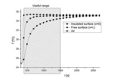
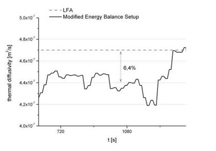
A Laser Flash device (NETZSCH, Nano Flash LFA447) was used to evaluate error in thermal diffusivity estimation using described methodology above. A polystyrene sample was measured. Figure 4 shows temperature evolution during the test and figure 5 compared results between Laser Flash and modified energy balance setup.
|
Figure 4: Temperature evolution during test in modified energy balance setup. |
|
Figure 5: Thermal diffusivity results using LFA device and estimation from modified energy balance data analysis. |
As it is shown in figure 5, results obtained with modified energy balances setup are less accurate, but big samples can be tested and thermal conductivity of the composed material can be evaluated. Nevertheless, LFA measurements are more accurate. For LFA measurements small samples (maximum 2 millimetres thickness) are required. These two experimental setups, LFA and modified energy balance setup are then complementary.
Using the experimental setup presented in this work previous analysis of transient thermal behaviour of building materials is done. It has special interest for those materials that is not possible to have small samples to test in more precise devices like Laser Flash. This methodology has promising results and work is going to continue in this field.
Nowadays, the most interesting application of this setup is to compare thermal response of building materials containing phase change materials and without containing.
Authors would like to thank Spanish government for supporting this work done in the research project ENE2005-08256-C02-02/CON.
[1] B. Zalba, J. M. Marin, L. F. Cabeza and H. Mehling, Applied Thermal Engineering, Vol. 23 (2003) pp. 251283.
[2] M. J. Huang, P. C. Eames and N. J. Hewitt, Solar Energy Materials and Solar Cells, Vol. 90 (2006) pp. 1951-1960.
[3] Y. Zhang, K. Lin, Y. Jiang and G. Zhou, Energy and Buildings, Vol. 40 (2008) pp. 1771-1779.
[4] F. Kuznik, J. Virgone and J. Noel, Applied Thermal Engineering, Vol. 28 (2008) pp. 1291-1298.
[5] Carbonari, M. De Grassi, C. Di Perna and P. Principi, Energy and Buildings, Vol. 38 (2006) pp. 472-483.
[6] N. Sarier and E. Onder, Thermochimica Acta, Vol. In Press, Corrected Proof.
[7] M. A. Medina, J. B. King and M. Zhang, Energy, Vol. 33 (2008) pp. 667-678.
[8] P. Schossig, H.-M. Henning, S. Gschwander and T. Haussmann, Solar Energy Materials and Solar Cells, Vol. 89 (2005) pp. 297-306.
[9] L. F. Cabeza, C. Castellon, M. Nogues, M. Medrano, R. Leppers and O. Zubillaga, Energy and Buildings, Vol. 39 (2007) pp. 113-119.
[10] D. P. Bentz and R. Turpin, Cement and Concrete Composites, Vol. 29 (2007) pp. 527-532.
[11] D. A. Neeper, Solar Energy, 68(5) (2000) pp. 393-403.
[12] B. Zalba, J. M. Marin, L. F. Cabeza and H. Mehling, International Journal of Refrigeration-Revue Internationale Du Froid, Vol. 27 (2004) pp. 839-849.
[13] C. Castellon, M. Medrano, L. F. Cabeza, M. E. Navarro, I. Fernandez, A. Lazaro, B. Zalba. Eurosun 2008
There are different sorption principles that can be used for heat storage. An absorption technique is used in a commercial device that can provide 20 kW of heat and 10 kW of cooling from a solar source, the TCA from company Climatewell in Sweden. Extensively monitored during Task 32, it is more a chemical heat pump than a true storage.
It can however store energy for a few hours and convert hot water to cooling and heating. The principle is that when using one tank containing water (evaporator), and an other one containing an hygroscopic salt (reactor), water will evaporate to the salt that absorbs the water. When the confine /
space is in a state of vacuum the water transport will be so high that the water will start boiling in order to produce vapour at the same speed as it is absorbed by the salt. Such evaporation requires energy. If the energy is not supplied from outside the system it will be taken from the water itself, which as a consequence gets colder
Other techniques based on adsorption principles tried to use silicagel or zeolite as a storage medium. After extensice search in laboratory in Switzerland and in an experimental house in Austria, both media showed limitations in terms of usable temperature lifts during discharge when used as particles in beds. A new way to use zeolite has being developed in Germany within Task 32. An extruded solid zeolite with air channels showed interesting properties at laboratory level. Simulation showed that a 8 m3 storage volume would be enough for 70% of the heating load of a low energy house. A laboratory prototype will deliver more information soon.
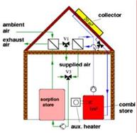 Fig. 7. The Monosorp storage concept from ITW, Germany is still a laboratory prototype but could lead to a dense seasonal storage solution for one family house.
At Empa in Switzerland, a prototype of storage unit based on the NaOH desorption at 150 C principle has been set up. First results show that the material can dry in summertime even better than anticipated (65% concentration reached) reducing the needed charging temperature to 120 C. The pilote installation will be monitored during 2 years and modelling will enlarge the scope of the results.
|
DTf • T + T J. 1^*0 ) |
|
m |
|
dt |
|
2 |
|
(eq.13) |
The differential equation governing the heat transfer into the fluid during the discharging process is given by equation 13.
|
Time (s) Fig.6: Comparison between experience (interface absorber/polymer (o) and outlet (□) temperatures) and simulation (interface absorber/polymer (—) and outlet (—) temperatures) in discharging process |
 |
This expression links the outlet temperature to the absorber temperature via a heat transfer coefficient hf-a calculated previously during preliminary absorber efficiency test (hf-a=70 W. m-2.K-1). Entering the experimental conditions (mass flow of 40L. h-1 and inlet temperature of 298 K) we obtain the profile temperatures plotted in figure 6.
|
G |
Solar global irradiation (W. m-2) |
h |
Heat transfer coefficient (W. m-2.K-1) |
|
m |
Mass flow (kg. s-1) |
m |
Mass (kg) |
|
T |
Temperature (K) |
||
|
Greek symbols |
|||
|
a |
Absorbance |
T |
Transmittance |
|
X |
Thermal conductivity (W. m-1.K-1) |
є |
Emissivity |
|
n |
Efficiency |
p |
Reflectivity |
|
Subscript |
|||
|
amb |
Ambiant |
c |
Composite |
|
e |
End |
f |
Fusion, Fluid |
|
i |
Inlet |
in |
Initial |
|
l |
Liquid |
o |
Outlet |
|
s |
Solid |
sky |
Sky |
Saunier Duval industry part of Vaillant Group and the French Government (trough the ANRT) are
acknowledged for financial support.
[1] J. Tey, J. I. Rosell, M. Ibanez, R. Fernandez, “Solar collector with integrated storage and transparent insulation cover”, poster at Eurosun 2002, Bologna, Italy, June 2002.
[2] Y. Rabin, I. Bar-Niv, E. Korin, B. Mikic, Integrated solar collectors storage system based on a salt hydrate phase change material, Solar Energy, Vol.55, No 6, pp. 435-444, 1995.
[3] D. Haillot, X. Py, V. Goetz, M. Benabdelkarim, Storage composite for the optimisation of solar water heating systems, Chemical Engineering Research and Design, Vol.86, Issue 6, pp. 612-617, 2008.
[4] Installations solaires thermiques et leurs composants — Capteurs solaires — partie 2: Methode d’essai, Norme europeenne prEN 12975-2, 2005.
[5] D. Faiman, Towards a standard method for determining efficiency of integrated collector-storage solar water heaters, Solar Energy, Vol. 33, No. 5, pp. 459-463, 1984.
[6] J. Duffie, W. Beckman, Solar engineering of thermal processes, Third edition, Wiley, 2006.
[7] J. Bernard, Energie solaire calculs et optimisation, Ellipses, 2004.
[8] C. Plantier, Etude numerique et experimental d’un prototype de chauffe eau solaire equipe d’un stockage a chaleur latente, these de doctorat, universite de Savoie, 2005.
A crucial step in the design and development of a cost and energy efficient storage is a comparative cost analysis. Here, the cost and capacity of conventional hot water storage and a PCM-storage have been examined. Below, the details of this study are summarized, and the results are shown and discussed.
For the comparative cost analysis, it is assumed that PCM storage and conventional hot water storage are to serve the same heat load in an identical solar hot water system. It is further assumed that the operating and maintenance cost (O&M) would be the same regardless of the choice of storage technology. Thus, the cost analysis only compares the first capital cost of conventional stratified hot water storage to those of PCM-based hot water storage with variable volume fraction of PCM. The volume fraction is here named the Ice Packing Factor (IPF). Table 1, below, summarizes the first cost categories comprising the heat storage.
|
Table 1. Example table caption for EuroSun 2008: papers accepted, by country.
|
The PCM considered here is a commercial PCM with a melting temperature around 58 °C, and with a latent energy storage capacity of around 71 Wh/kg. Its density is 1,46 kg/l giving a latent storage capacity of 103 kWh/m3. In the PCM concept, some additional storage capacity is also given by the sensible heat stored over some temperature range AT. In the analysis, this AT is assumed to be the same regardless of storage technology.
In the calculation, a PCM price of approximately 2.7 Euro/kg was used. This is a bit low as compared to what is possible to obtain today but was discussed with a leading manufacturer as being a reasonable target price for the future assuming a larger scale production and sales.
Finally, the price of the tank is an approximate figure obtained by a Swedish manufacturer of stainless steel tanks suitable for this application.
The work of Subtask B has shown that there are promising chemical and sorption storage solutions that should be further developed and tested at least in field trials. One concept has gone from prototype to commercialisation in the time period of Task 32, where short term storage for both heat and cold is utilised. The work has also shown that current materials are a limitation for the processes that have been studied, both for short and long term storage. Simulation models have been developed and used for system simulations. These show that high fractional energy savings are possible using seasonal storage for single family houses. Economics have not been considered.
The following areas are suggested for future work in the field:
• Research in materials for seasonal storage. This is required for closed three-phase absorption, open and closed adsorption as well as chemical reactions. The current materials are either too expensive, do not have the correct properties, or have not yet been shown to work in prototypes with realistic boundary conditions. Fundamental materials research is needed to get a better understanding of the physicochemical mechanisms.
• The numerical modelling of the heat and mass transfer processes in thermochemical materials is still very basic. Model improvement will result in new tools to better understand the dynamic behaviour of the materials processes and assist the material development in this field.
• For short term storage, research is required to find suitable materials and operational conditions that give a suitable temperature lift for cooling and heating together with sufficiently high energy density for storage. The cost of the material is not as important as for seasonal storage, but it is still an important factor.
• Studies on sources of low grade heat for heat pumping using closed processes. The sorption (and chemical reaction) processes studied in this Subtask, all use water. This needs to be evaporated before it is recombined with the active substance. This energy has to be either extremely low cost or free, and additionally has come from a heat source of at least ~5°C.
• The Monosorp concept is very promising and is suited for a full scale field test. However, at present their is no commercial method for extruding the zeolite monoliths required in the store.
• Seasonal stores are not charged once and then discharged. During autumn and spring there are periods with both charging and discharging. The store operates at different temperatures for these two states. More study is required to understand how best to recover the sensible heat during these changes in store temperature and whether it is best to segment the store so that only smaller portions undergo these changes.
[1] Hadorn, J.-C., ed. Thermal Energy Storage for Solar and Low Energy Buildings.- State of the Art. 2005, Lleida University: Lleida, Spain. ISBN: 84-8409-877-X.
[2] Visscher, K., Veldhuis, J. B.J., Oonk, H. A.J., Van Ekeren, P. J. and Blok, J. G. Compacte chemische seizoensopslag van zonnewarmte, 2004, ECN report C04074.
[3] Bales, C., et al. IEA-SHC Task 32 report: Project Report B2 of Subtask B: Thermal Properties of Materials for Thermo-chemical Storage of Solar Heat, IEA-SHC, Paris, France.www. iea-shc. org. 2005.
[4] Bales, C., et al. IEA-SHC Task 32 report: Project Report B4 of Subtask B: Laboratory Tests of Chemical Reactions and Prototypes Sorption Storage Units, IEA-SHC, Paris, France.www. iea-shc. org. 2008
[5] Herbert Zondag, Martijn van Essen, Zeming He, Roelof Schuitema, Wim van Helden, Characterization of MgSO4 for thermochemical storage in Second International Renewable Energy Storage Conference (IRES II), 2007, Bonn, Germany.
[6] Zondag, H. IEA-SHC Task 32 report: Project Report B6.1 of Subtask B: Simulation report — System:
ECN TCM model, IEA-SHC, Paris, France.www. iea-shc. org. 2008
[7] Bales, C. and S. Nordlander, TCA EVALUATION — Lab Measurements, Modelling and System Simulations. 2005, SERC, Hogskolan Dalarna: Borlange, Sweden. ISRN DU-SERC—91—SE. www. serc. se.
[8] Bales, C. Solar Cooling and Storage with the Thermo-Chemical Accumulator. in Eurosun 2006. 2006. Glasgow, UK.
[9] Bales, C., et al. IEA-SHC Task 32 report: Project Report B5 of Subtask B: Store Models for Chemical and Sorption Storage Units, IEA-SHC, Paris, France.www. iea-shc. org. 2008
[10] Bales, C., et al. IEA-SHC Task 32 report: Project Report B7 of Subtask B: Final report of Subtask B “Chemical and Sorption Storage” — The overview, IEA-SHC, Paris, France.www. iea-shc. org. 2008
[11] Heimrath, R. and M. Haller IEA-SHC Task 32 report: Project Report A2 of Subtask A: The Reference Heating System, the Template Solar System of Task 32, IEA-SHC, Paris, France.www. iea-shc. org. 2007
[12] Letz, T., et al. IEA-SHC Task 32 report: Project Report A3 of Subtask A: Performances of solar combisystems with advanced storage concepts, IEA-SHC, Paris, France.www. iea-shc. org. 2007
[13] Letz, T., et al. IEA-SHC Task 32 report: Project Report A1 of Subtask A: The extended FSC procedure for large storage capacity, IEA-SHC, Paris, France.www. iea-shc. org. 2007.


The structure was done using 4 mortar pillars, also with reinforcing bars, one in each edge of the cubicle. The base consists of a mortar base of 3×3 meters with crushed stones and reinforcing bars. The walls consist of perforated bricks (29x14x7.5 cm, Fig. 2) with an insulating material (depending on the cubicle) on the external side and plaster on the internal side. The external finish was done with hollow bricks and a cement mortar finish. Between the perforated bricks and the hollow bricks there is an air chamber of 5 cm. The roof was done using concrete precast beams and 5 cm of concrete slab. The internal finish is plaster. The insulating material is placed over the concrete, protected with a cement mortar roof with an inclination of 3% and a double asphalt membrane.
Three cubicles using different insulating materials are compared:
1. Reference cubicle: This cubicle has no insulation.
2. Polyurethane cubicle: The insulation material used is 5 cm of spray foam polyurethane.
3. PCM cubicle: The insulation used is again 5 cm of spray foam polyurethane and an additional layer of PCM. CSM panels (Fig. 3) containing RT-27 paraffin are located between the bricks and the polyurethane (in the southern and western walls and the roof).
The most important properties of the insulation materials and the PCM are shown in Table 1 and Table 2.
|
Fig. 2 Hollow brick |
|
Fig. 3 CSM panel containing the PCM. |
|
Fig |
|
4 Demonstration cubicle built with brick. |
|
Fig. 6 Demonstration cubicle built with brick, RT-27 and polyurethane. |
|
Table 1 Physical properties of polyurethane.
|
|
Table 2 Physical properties of RT-27.
|
|
Fig. 5 Demonstration cubicle built with brick and polyurethane. |
 |
|
 |
 |
From Fig. 4 to Fig. 6 it is shown the demonstration cubicles built with brick, polyurethane, mineral wool, polystyrene and with brick, RT-27 PCM and polyurethane.
A thermal network based on a control volume finite difference discretisation of the house was used. The model used was implemented in MATLAB [4]. Two zones were used: a basement zone and the rest of the building. MATLAB subroutines were written to model the performance of the BIPV/T system, the heat exchanger/heat pumps group, the ground source/HPs interaction, and the TES reservoir.
The BIPV/T model [1, 3] was based on dividing the channel lengthwise in a given number of sections, assuming uniform temperatures at the top and bottom surfaces. An exponential profile is assumed within each section; temperatures and heat transfer rates are found iteratively using a 1-D thermal network between the air and the surfaces. The exit temperature of each section is used as the entrance temperature of the next section.
A simple model based on the variation of effectiveness of the heat exchanger with varying flow rates and manufacturer’s data was used to model the performance of the HX and one or both HPs
[2] . This model was modified to use an adjusted temperature of the ground as an input.
Finally, a 4-node simple model, as described in [5], was used to model the TES reservoir. In this model, the water in the TES is divided into four nodes (a convenient model since there are also four internal divisions in the tank). The water entering the tank (either from the radiant floor heating system or the HPs) is assumed to go to the node having the highest temperature below that of the incoming water. Simple water exchanges are then assumed to take place between the nodes to guarantee mass flow rate balance. According to [5], the use of 3 or 4 nodes is a good compromise between an accurate model and a conservative design (which would assume only one node).
|
(1) |
|
pC |
|
dT dt |
|
_d_ dz |
|
к |
|
дт dz |
|
+ q — q |
|
loss Fig.3.The physical structure of the coordinate system of the solar pond model |
 |
|
The system being considered is the one dimensional heat transfer problem through a parallel piped whose base is a unit surface area of the pond, and its height is the depth of the pond. To obtain better results from the model developed, it is more convenient to address each zone in respect to the boundary conditions. For this purpose, the pond is considered to have three zone, as in Fig 3. The UCZ and LCZ are considered as single grid points which have a thickness of Z0 and ZA, respectively. The total depth of the pond is Z. Conservation of energy is then applied on each zone. For NCZ, the energy equation ca be written as follow;
For LCZ, the energy equation is also written as follow;
dT
PCpADL^7 = QR — Qup — Qs — Qg — Ql (2)
dt
By assuming that the pond is well insulted, heat loss around the pond is small comparative with amount of heat extraction. The equation (2), thus, can be written as follow;
AT
Qsolar = Qs + mCp — (3)
|
Qsolar |
|
(4) |
|
Q thermosyphon |
|
+ mcp |
|
AT At |
From the fact that extracted heat from the solar pond is equal to the heat extracted by thermosyphon. Substitute (3) into (2), we got;
Estimation of solar pond’s heat absorption is expressed by Rubin et al.(1984), the heat from solar radiation of any location can be often.
Where ф is the rate of the solar radiation at any wave length pass though the pond in any depth z, can be obtained.
|
(6) |
![]() ф = ф0 n exp(-M z /c°s<92)
ф = ф0 n exp(-M z /c°s<92)
J =1
Substitute ф0and constant value from (6) into (5). Therefore, it follows that
4 Mj — p. z/cos# (7)
Ч(А = ф0 ^ exp J
0J=1 cos#
Hence, the calculation of energy balance at LCZ can be obtained from (4).