Как выбрать гостиницу для кошек
14 декабря, 2021
Сегодня каждый, кто собирается в отпуск и не знает, с кем оставить своего котика или кошку, может во[...]
The main findings of the studies on closed adsorption storage, as reported by EMPA in Switzerland, are the following:
• The heat capacity of the NaOH storage (2 stages) compared to a water storage is about 3 times better for domestic hot water (DHW) and about 6 times better for heating purposes (heating floor). The calculations are made for a building located in central Europe.
• The heat capacity of a one stage (one process unit per storage) system especially for DHW is insufficient. The above specified heat capacity is only given with a second stage.
• The storage is intended to be charged with solar energy with no auxiliary heater. To avoid too big storage volumes, the buildings must be built in low energy standard like “Passive House” or “Minergie” (Swiss standard).
• NaOH — lye as sorbent has a good cost benefit ratio. NaOH is a by-product of the PVC production and costs only about 250€/m3. The estimated volume of NaOH — lye for a passive house is about 5 m3. This figure depends strongly on the climate and the used solar collector area.
• The separation of the process units and the tanks into independent modules, leads to a simple control strategy. In the process unit, there are only small amounts of mass of the chemical process involved. This allows continuous operation.
A. Castell, M. Medrano, C. Castellon, Luisa F. Cabeza
GREA Innovacio Concurrent, Edifici CREA, Universitat de Lleida, Pere de Cabrera s/n, 25001-Lleida (Spain)
Phone: +34-973 003576, Fax: +34-973 003575 Corresponding Author, [cabeza@diei. udl. cat
Abstract
This work presents an experimental set-up to test phase change materials with various typical insulation and construction materials for Mediterranean construction in real conditions. Several cubicles were constructed with traditional brick and alveolar brick. Macroencapsulated PCM is added in one traditional brick cubicle and in one alveolar brick cubicle (CSM panels, containing RT-27 and SP-25 A8, respectively).
Some experimental results are presented for both summer and winter periods. In summer the energy consumption of the HVAC system was reduced in the PCM cubicle for set points higher than 20 °C. Lower set points decreased the effect of the PCM since it is not melting properly (the melting point of the PCM is around 26 °C). During winter an insulation effect of the PCM is observed, keeping the temperatures of the cubicles warmer, especially during the cold hours of the day.
Keywords: PCM, buildings, cooling, thermal energy storage.
Energy consumption for thermal comfort in buildings has grown a lot in few years because of increasing users demand for comfort conditions and the associated market penetration of more cooling systems. This increase of energy consumption and the increase of the fuel price and CO2 emissions are promoting a new policy of more sustainable buildings.
Phase change materials (PCMs) have been studied for thermal storage in buildings since before 1980.
In first steps, development and testing were conducted for prototypes of PCM wallboard and PCM concrete systems to enhance the thermal energy storage (TES) capacity of standard gypsum wallboard and concrete blocks, with particular interest in peak load shifting and solar energy utilization.
Several researchers have investigated methods for impregnating gypsum wallboard, concrete and other architectural materials with phase change materials [1-3]. Different types of PCMs and their characteristics are described. The manufacturing techniques, thermal performance and applications of gypsum wallboard, concrete block and concrete with microencapsulated PCM which have been impregnated with phase change materials have been presented and discussed previously [4-7].
This work presents a new experimental set-up to test the effect of the inclusion of PCM in buildings. For this purpose, several cubicles were constructed using traditional brick and alveolar brick.
Macroencapsulated PCM is added in one traditional brick cubicle and in one alveolar brick cubicle (CSM panels, containing RT-27 and SP-25 A8, respectively).
Two ducts bring the hot air from the roof to an air-to-water heat exchanger (HX). Due to its size (cross-section of approximately 1.2 m x 1 m) this HX is located in the ceiling of garage. The HX allows the use of the BIPV/T to heat the water in a large reservoir in one of two ways: (a) directly, via a piping system connecting it to a coil inside the TES tank; or (b) by using the hot air to heat the water of the source side of two twin heat pumps (HPs). System (a) can be used when the BIPV/T air temperature is considerably higher than that of the bottom of the tank. During the winter, however, the BIPV/T air temperatures will often be between 10 and 30 °C, which is an optimal source temperature range for the operation of the HPs. The details of the selection of these HPs have been described elsewhere [3]. Each heat pump is rated at 10.6 kW. They can operate together or one at a time, extending the range of air flow rates that can be useful to provide thermal energy; it has been rated from about 400 to 1000 L/s.
The aforementioned large water reservoir represents the main active thermal energy storage (TES) of the ANZEH. Its volume (about 4000 L) permits storing about one day’s worth of heating for a heating load of 6 kW. Apart from the coil making the direct link to the HX, and the pipes connecting it to the HPs, the TES tank has an additional coil connecting it to the domestic hot water (DHW) tank. The TES tank will deliver the thermal energy to a plate heat exchanger, which in turn transfers heat to a low temperature radiant floor heating system installed in the concrete slabs in the basement, main and upper floors. A vertical division, and two adjustable horizontal baffles with a perforation in the centre, will enhance the thermal stratification of the tank.
However, the main factor limiting this stratification is the high flow rates required by the HPs; the temperature difference between the maximum and minimum temperature in the tank will be about 5-8 °C.
2.2. ![]()
|
Fig. 8. Ground plan |
 |
Ground plan of the building
This project demonstrates that ecology is not inconsistent with economy. Innovative building technology and use of solar energy go hand in hand.
Heat transfer in the sample is assumed to be one-dimensional because temperatures are measure at centre of surfaces. A differential element in the centre of the sample is taken as volume of control. Equation 1 describes heat transfer in this volume of control.
d2T (x, t) _ 1 dT (x, t)
dx2 a dt (Ec.1)
Where,
X 2
a _ thermal difussivity _ [m / s]
P-cp
X _ thermal conductivity [W /(m — K)]
p _ density [kg / m3 ]
cp _ heat capacity [ J /(kg — K)]
In the experimental setup boundary conditions are:
|
. at ^ |
|
dx*2 dFo |
|
= — Bi в*(1,Fo) |
|
Solution for infinite plane wall is: ад в = X Cn exp(^n2 • Fo) • cos(^n • x*) n=1 C = 4 • sen(L) n 2 •£, + sen (2 •£,) In cases that Fo>0.2: в* = C1 exp(<^2 • Fo) • cos(^1 • x*) = в0* cos(^1 • x*) в0* = в*(x* = 0, Fo) = C1 • exp(<^2 • Fo) |
|
(Ec.2) |
![]()
|
(Ec.3) |
|
(Ec.4) |
|
dT_ dx |
|
x=0 |
|
= 0 |
|
-A |
|
dT_ dx |
|
h [T (T, t) — Tf ] |
|
x=L |
|
The problem can be expressed using non dimensional variables: |
|
* x x = — L |

|
(Ec.5) (Ec.6) (Ec.7) |
|
(Ec.8) (Ec.9) |
|
(Ec.10) (Ec.11) |
|
в T — Tf |
|
в T — Tf |
|
д в дв |
|
дв |
|
dx двв |
|
= 0 |
|
x =0 |
|
dx |
|
x =1 |
|
Bi = |
|
hL T: |
|
where h = forced heat convection coefficient |
T (x = 0, t = 0) = T
For each instant measured, Biot and Fourier number are obtained, and then thermal diffusivity is estimated.
One way to improve storage is to use a material that can be more energy dense than water. If the transition temperature is adequately chosen, such materials exist. Task 32 worked with sodium acetate which exhibits a theoretical transition point at 58 C, ideally suited to solar combisystems.
Material caracterisation is a topic in itself and Task 32 developped a method to be able to assess the thermal properties of the material in a confident and repeatable way (figure 4).
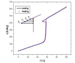 Fig. 4. Thermal properties of sodium acetate trihydrate with graphite, measured at IWT, Austria. The material supercooling effect is clearly visible. Hysteresis must also be precisely measured.
Modelling PCM in a storage is also a difficult item that has been adressed by Task 32. We have now models of sodium acetate in different configurations that can be used to predict the behaviour of solar combisystems with such PCM storages.
Simulation of several combisystems with PCM storage revealed that PCM storage show two unforeseen limitations: the volume of PCM that one can introduce into a water tank is limited to 20 to 30% of the whole storage volume, due to the necessary containment of the material and the heat extraction power from PCM to water is limited by the diffusion process inside the material. Sodium acetate did not show a decisive advantage over water in a combitank even if its density of energy is higher and if its heat conductivity is enhanced with graphite. Special system design were developped which showed better improvements but with a 35 C transition temperature material.
Fine tuning of the adequate PCM and the proper way to build an efficient heat exchange should remain on the agenda of international solar research. A new idea is being investigated in Denmark: using the supercooling effect of sodium acetate to build a seasonal store with limited heat losses.
During the charging process, as no fluid flows through the absorber, the calculated absorber temperature is directly linked to the composite temperature at the interface by:
|
— к |
![]()
|
c |

|
К / a (Tc — T ) |

![]() (eq.12)
(eq.12)
|
Fig.5: Comparison between experience (interface absorber/polymer (o), interface PCM/polymer (A) and polymer (□) temperature) and simulation (interface absorber/polymer (—) and polymer (—) temperature) in charging process |
 |
With an exchange coefficient of 130 W. m-2.K-1 we obtain the temperature profile plotted in figure 5. The simulated temperature profile at the middle of the composite is situated between the two recorded experimental temperatures.
V. Martin*, F. Setterwall and L. Hallberg
Ecostorage Sweden AB, Backvagen 7c, SE-192 54 Sollentuna, Sweden
Corresponding Author, viktoria. martin@,ecostorage. se
Abstract
Solar heating in the built environment is a crucial component for minimizing the use of fossil fuel. However, an energy and cost efficient solar system requires some sort of integrated storage. Here, high energy density and high power capacity for charging and discharging are desirable properties of the storage. This paper presents the results and conclusions from the design, and experimental performance evaluation of high capacity thermal energy storage using so-called phase change materials (PCM) as the storage media.
A 15 kWh PCM-based storage was designed, built, and experimentally evaluated with regards to capacity and power properties. The storage had a volume of close to 140 liters such that the specific storage capacity was around 100 kWh/m3 and the ice packing factor (IPF) was close to 80%. The first results from the experimental evaluation show that the storage can provide hot water with a temperature of at least 40 °C for more than two hours, at an average power of 3 kW.
A comparative cost analysis show that, considering the capital (first) cost only, the cost of the PCM-storage is always higher than for a water storage (i. e. IPF=0) although the difference is not very large. However, if the cost of “space requirement” is important, such as in a house, the PCM — solution quickly becomes cost effective as compared to the hot water storage.
Keywords: PCM, phase change materials, latent heat, thermal energy storage, solar hot water
Solar heating in the built environment has the potential to aid in minimizing the use of fossil fuel. However, an energy and cost efficient solar system requires some sort of integrated storage with high energy density and high power capacity for charging and discharging being desirable properties of the storage. By using conventional hot water storage with a 30 °C temperature difference, it is possible to store about 30 kWhheat/m3 storage. By an appropriate design of thermal energy storage using phase change material-technology (PCM) it is possible to triple the capacity to over 90 kWh/m3. Hence, PCM-storage has been explored extensively over the years, and this work is thoroughly summarized by Hauer et al. [1]. Earlier, most studies focussed on the storage capacity (energy) rather than the importance of also having a large power capacity for charging and discharging. However, one problem with PCM-technology is the relatively low conductivity of PCM resulting in low power for charging and discharging. This important design challenge has recently been addressed in several ways. Recently, for example, Seeniraj and Narasimhan [2] theoretically modelled a finned tube submerged in
multiple PCMs with varying phase change temperature. With the multiple PCMs it is possible to maintain a higher temperature difference between the heat transfer fluid and the PCM throughout the charging process. The results showed a possibility for a much higher rate of melting using this concept, as compared to only a single PCM. Also, the exit temperature of the heat transfer fluid was held constant over time. Pincemin et al [3] also modelled tubes submerged in PCM with added graphite powder to enhance conductivity. To further improve the conductivity, graphite fins were submerged between the tubes. The conclusion was that there is an optimal proportion between the amount of graphite added as powder and the fin spacing for the graphite fins.
For the purpose of developing cost effective PCM-based storage for solar applications, a 15 kWh PCM-based storage was designed, built, and experimentally evaluated with regards to capacity and power properties. The design features were chosen to obtain high power, high storage capacity and low manufacturing cost.
The storage concepts have been compared in a number of different aspects including storage density, cost for materials, temperature requirements as well as system simulation results (for three of the concepts) with the same boundary conditions [11]. Data from lab testing of prototypes [4] and estimations of storage size for 70 and 1000 kWh storage capacity showed the following:
• The storage density for cold (based on total system volume), when compared to water, is more favourable than for heat. For the ClimateWell 10 commercial heat pump/store, the storage density for cold is 4.7 that of water whereas for heat it is only 1.2 times greater. This is due to the fact that the temperature range available for water storage for cold is smaller (~10°C) than for heat (~60°C).
• For short term heat storage, the best technologies have an energy density 2 — 2.5 times that of water. This is relatively low due to the space required for reactors and condenser/evaporator in addition to the store. In addition all of the storage systems have irreversibilities in the processes themselves during charge and discharge resulting in lower store efficiencies.
• For longer term storage (1000 kWh) the energy density for the TCA technology and NaOH storage systems is nearly three times that of water, for Monosorp twice and for MgSO4.7H2O 2.5.
In addition, once the sensible heat from the solution has been lost (or at best recovered), the energy can be stored indefinitely, a significant advantage compared to water.
• In terms of material cost, all materials are expensive compared to water. However, NaOH, is significantly less expensive than the other materials reported: zeolite, LiCl, silica gel,
MgSO4.7H2O and zeolite 13X. The cost for the whole storage system has not been estimated here. For the ClimateWell 10, the projected cost is ~8000€ for a heat pump system consisting of two units in parallel, with a total heat storage capacity of 70 kWh.
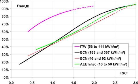
The fractional energy savings (Fsav, th) of three systems, based on system simulations are shown in Fig.2. FSC’ [13] is a quantity that reflects the theoretical amount of energy a system with given boundary conditions can save, if it is 100% efficient from solar to heat delivery. It is dependent on the amount of radiation incident on the collector, and thus collector size, orientation and slope, and heat demand. It is also dependent on storage capacity. Systems with a large storage capacity
compared to the load can have an FSC’ value larger than 1, while systems with small heat capacity have a maximum FSC’value of near 1. The curves show that the performance of the AEE Intec closed adsorption system and that of the ECN chemical storage system are fairly similar, if the storage size of the ECN system is similar to that of the AEE Intec system. A larger storage size gives improved savings. The ITW Monosorp open adsorption system achieves significantly greater savings compared to the others. This is partly due to the fact that the collector is slightly better, but also because the system uses a ventilation heat recovery system that is not in the other systems. This means that the Monosorp system in practice has a smaller space heating load than the other systems, which automatically results in greater savings without affecting the FSC’value.
|
Fig. 2. FSC’ characteristic curves derived from simulations for three chemical and sorption systems [12]. |
It must be pointed out that these simulation results are for systems in different stages of development, using models with different degrees of detail. The curves are also trendlines for a number of points, with dotted sections being extrapolations.
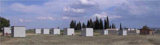
The cubicles were built with Mediterranean typical constructive solutions. To be able to compare the results obtained with the concrete cubicles studied previously [7], the internal dimensions of the new cubicles are the same as the old ones (2.4×2.4×2.4 meters). Fig. 1 shows the demonstration cubicles built with concrete.
|
Fig. 1 Demonstration cubicles built with concrete. |
For a good comparison of the new cubicles there are no windows. One door in the northern wall is the only opening of the new cubicles.